Electromagnetic field analysis software

Electromagnetic field analysis software
Parallel computing capability with OpenMP
- TOP >
- Analysis Examples by Functions (List) >
- Parallel computing capability with OpenMP
Summary
EMSolution has been developed with the aim of achieving large scale and high speed analysis of electromagnetic field. In recent years, as multi-CPU and multi-core machines have become more common, we have added a parallel function, albeit partially, to EMSolution.
Note that parallelization is based on OpenMP, which can be performed on a single node (one WS), so parallel computing beyond the number of cores installed is not possible. However, it is suitable for relatively large 3D analyses because of the speedup effect that can be easily achieved by the number of units. The following three parallel functions are introduced in this issue. We plan to parallelize the other parts of the system as well.
- Parallel computation of ICCG method
- Parallel computation of B_INTEG
- Parallel Processing in MeshedCOIL
Explanation
Parallel computation of ICCG method
The ICCG method is a linear symmetric matrix solution method used for ordinary static and transient magnetic field analysis. It can be used regardless of whether the magnetization characteristics are linear or nonlinear. Please note that it is not applicable to two-dimensional magnetic anisotropy where the matrix is asymmetric. The BlockICCG method is used for parallelization of the ICCG method, and a part of the Newton-Raphson method used in the calculation of nonlinear magnetization properties is also parallelized.
As an example, we show the results of applying this method to the generator model shown in Fig. 1 and the three-dimensional analysis of the concentrated winding IPMSM (D1 model), which is the benchmark model of the Institute of Electrical Engineers of Japan. The analysis is a nonlinear transient magnetic field analysis with a current source; Table 1 and Fig. 2 show the generator model, and Table 2 and Fig. 3 show the number of units effect for the concentrated winding IPMSM. For the generator model with good convergence, the number effect is almost linear for 2 and 4 parallel systems. For the D1 model, the convergence is not so good, and the number effect drops slightly for the 4-parallel model. This is because the BlockICCG method performs BlockIC decomposition, so convergence becomes worse as the number of parallelism increases, and the number of ICCG iterations tends to increase. However, the calculation is 1.9 times faster than with a single (one-parallel) calculation.
Thus, it can be said that parallelization by the BlockICCG method is useful because the computation time can be shortened simply by increasing the number of parallels. Note that the effect of the number of units seems to strongly depend on the performance of the CPUs installed. The machine used in this example has an Intel Xeon E5520 (64bit, Nehalem) CPU, 2.26GHz, 4 cores, and 12GB memory. Hyperthreading is not used. It seems to be a CPU that can easily produce a unit number effect.
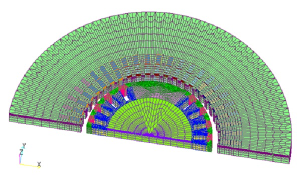
(a) Generator model: Number of elements 143,180
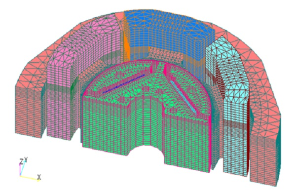
(b) Concentrated Volume IPMSM Model: Number of elements 412,776
Fig.1 Analysis model
Table1 Effect of Number of Generators Model
| Number of parallels | Computation time (s) | Number of ICCG iterations | Number of NR iterations |
|---|---|---|---|
| 1 | 184.4 (1.00) | 733 (1.00) | 15 (1.00) |
| 2 | 118.3 (1.56) | 763 (1.04) | 15 (1.00) |
| 4 | 85.8 (2.15) | 824 (1.12) | 15 (1.00) |
Table 2: Number Effects of the Concentrated Volume IPMSM Model
| Number of parallels | Computation time (s) | Number of ICCG iterations | Number of NR iterations |
|---|---|---|---|
| 1 | 391.8 (1.00) | 2946.2 (1.00) | 7.5 (1.00) |
| 2 | 232.6 (1.68) | 2982.1 (1.01) | 7.4 (0.99) |
| 4 | 206.8 (1.89) | 3451.7 (1.17) | 8.9 (1.18) |
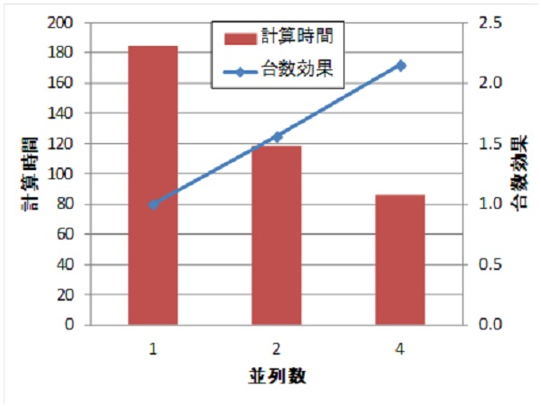
Fig.2 Effect of number of cores on computation time
– Generator model –
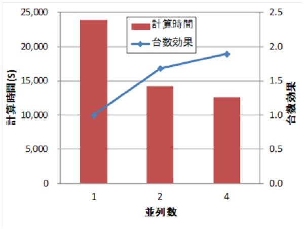
Fig.3 Effect of number of cores on computation time
– Concentrated winding IPMSM model –
Parallel computation of B_INTEG
A parallel calculation function has also been added to "B_INTEG (Calculation function of spatial fields generated by magnetization and currents by integration)". This allows the output of the magnetic flux density at any position with high accuracy, independent of the mesh geometry, for spatial magnetic fields other than those of magnetic materials and conductors. This is very suitable for parallel computation, and thus produces the ideal number of units effect.
As an example, we will verify the effect of the number of units on the model used in the "magnetic field distribution calculation for coils only" shown in Fig. 4. The evaluation points are arranged in a grid of 0 to 250 mm in each axis direction, divided into (1) 50 equal parts and (2) 100 equal parts. Table 3 shows the effect of the number of units. It can be seen that the effect of the number of units is almost ideal. The machine used is a Quad Core Intel Xeon 3.00GHz x 2 CPU (total 8Core). It seems that this function can obtain the number effect regardless of the CPU.
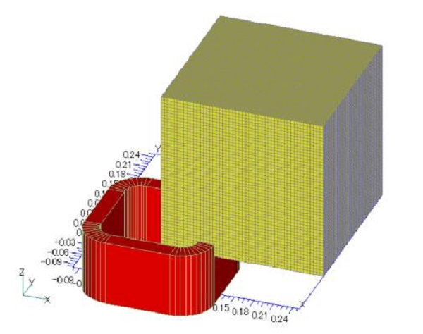
Fig.4 COIL and magnetic field evaluation mesh
Table3 Effect of the number of parallels
| B | 100 divisions | 50分割 | ||
|---|---|---|---|---|
| Number of Threads | Computation time (sec) | number effect | Computation time (sec) | number effect |
| 1 | 24.656 | 1.000 | 3.282 | 1.000 |
| 2 | 12.516 | 1.970 | 1.656 | 1.982 |
| 4 | 6.344 | 3.887 | 0.844 | 3.889 |
| 8 | 3.188 | 7.734 | 0.438 | 7.493 |
| Rating Points | 1,030,301 | 132,651 | ||
Parallel Processing of MeshedCOIL
Parallel processing has also been added to the processing of MeshedCOIL described in "Definition of COIL (external current field source) by hexahedral element meshes". This function allows the definition of COIL with hexahedral finite element meshes, and the amount of calculation is proportional to the number of hexahedral elements and integration points. During this process, parallel processing is performed COIL_INDUCTANCE described in "COIL inductance and electromagnetic force calculation", REGULARIZATION function that guarantees current continuity as described in "Nonlinear Option Comparisons", and the magnetic flux density output.
As an example, the armature coil of the generator model shown in Fig. 5 (different from Fig. 1) can be modeled with MeshedCOIL, including the coil ends. The field coil of the rotor is modeled with COIL. The meshedCOIL of the armature coil is modeled with a full circumference model because the reduced potential region in the finite element mesh includes periodic boundary conditions, so symmetry as in the finite element mesh cannot be applied. The COIL of the field coil can be modeled only in the finite element region because the Reduced Potential region is only around the COIL that does not touch the periodic boundary. Since COIL is used in the rotor and stator, Multi-potential method described in "About multi-potential method" is used. Due to the long time-constant resulting from the use of a voltage source, the TP-EEC method is required for this model, and the parallel functions of the Meshed_COIL and ICCG methods can be applied.
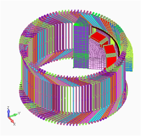
Fig.5 Generator model
Although the scope of application of the parallel computing capability with OpenMP is still limited, we believe that we have demonstrated that the parallel computing capability with OpenMP is useful. As further large-scale analysis is becoming essential, we hope you will try it out. We also accept evaluations before installation, so please feel free to contact us from "here".
How to use
Parallel computing capability with OpenMP
The option PARALLEL_NO (Number of parallel computations) has been added to the Handbook "4 Order of the Shape Function and Added Features". This single option allows you to set whether or not parallel calculations are performed.
This will cause parallel computation if the number of cores is less than or equal to the number of cores on the node performing the computation (but it depends on your license. Parallel module is required.). PARALLLEL_OPTION is an option when NON_LINEAR=1 (Nonlinear magnetization property) is selected for parallel computation of ICCG method, and you can select either =0: Speed-oriented and large memory usage or =1: Memory-oriented and small memory usage. If you do not have enough memory, it is recommended to use =1. Note that this calculation requires the Parallel module.
Since this function is a parallel calculation using OpenMP, it is a parallel calculation within a single node.
Download
ICCG method parallel computation data
D1 Model
Static magnetic field analysis for initial value calculation :
・ input3D_static20deg.ems : Input file
・ pre_geom2D.neu : Stator mesh data
・ rotor_mesh2D.neu : Rotor mesh data
・ 2D_to_3D : Rotor mesh data
Transient Analysis :
・ input3D_transient20deg.ems : Input file
・ pre_geom2D.neu : Stator mesh data
・ rotor_mesh2D.neu : Rotor mesh data
・ 2D_to_3D : Rotor mesh data
B_INTEG Parallel calculation data
Coil Model (COIL)
For 50 divisions :
・ input.txt : Input file
・ B_integ_mesh.NEU : Mesh data
Analysis Examples by Functions
Convergence property improvement and speed-up methods
- Problems with flat tetrahedral elements and their countermeasures
- Node-second-order edge-first-order elements
- Joining hexahedral and tetrahedral elements
- Improved convergence of flat and elongated elements
- Fast convergence to steady-state solutions of time-periodic problems
- Steady-State Analysis of Induction Motors Using a Simplified Time-Periodic Method
- Steady-State Analysis of Rotating Machines by Simplified Multi-Phase AC EEC Method
- Parallel computing capability with OpenMP
- Restart analysis function for changing convergence conditions
©2020 Science Solutions International Laboratory, Inc.
All Rights reserved.