Electromagnetic field analysis software

Electromagnetic field analysis software
Steady-State Analysis of Induction Motors Using a Simplified Time-Periodic Method
- TOP >
- Analysis Examples by Functions (List) >
- Steady-State Analysis of Induction Motors Using a Simplified Time-Periodic Method
Summary
In "Induction Motor Analysis", we showed that the approximate steady-state solution of a cage induction motor can also be obtained by AC steady-state analysis, and that a time-step analysis using this as the initial value can quickly obtain a steady-state solution. Since AC steady-state analysis is a linear calculation, it is necessary to give an appropriate permeability. Since AC steady-state analysis is a linear calculation, it is necessary to give an appropriate permeability. However, when nonlinearities are strong, such as in the case of an induction motor with a solid rotor, the results of a linear steady-state analysis will often differ significantly from the steady-state solution. In such cases, even if a time-step analysis is performed with the AC steady-state solution as the initial value, it will take a large number of steps to reach the steady-state solution. As introduced in "Fast Convergence to Steady-State Solutions of Time-Periodic Problems", the SD-EEC time-periodic finite element method for synchronous rotating machines can rapidly obtain a steady-state solution. However, this method cannot be applied to induction machines with slippage, since corrections are made for both the stator and the rotor.
In induction machines, the period of one cycle of the armature current on the stator side does not coincide with the period of slip on the rotor side, but in steady state, the armature current and magnetic field are considered to have approximate semi-periodicity (sign reversal in half of one cycle) when viewed only in the stator. The time constants of the currents in the rotor bars and end rings of the rotor are considered to be smaller than those of the stator windings, and the aperiodicity due to the rotor is also considered to be small, making it possible to apply the half-periodic time-periodic method to the stator only. Therefore, we have developed a function to apply the time-periodic method to the stator only by utilizing this half-periodicity.
Explanation
The method applied is called the simplified time-periodic method. In the SD-EEC method, the correction equation is derived to obtain the correction amount, and the correction is made at each half-period or period, but in the simplified time-periodic method, the following correction is made for half-periodicity. In the time step analysis, for a solution $x_0$ of the equation at a certain point in time and a solution $x_1$ after a half period, the correction quantity $p$ is obtained by the following equation:
$$ p=-\displaystyle\frac{x_0+x_1}{2}$$
The correction is made for $x_1 \leftarrow x_1 + p$, and the subsequent analysis is also corrected for each half period. This is a simple method that does not require solving the equations for correction but compared to the SD-EEC time-period method, it seems to require a slightly larger number of corrections until a steady-state solution is reached.
The following is an example of applying the simplified time-periodic method to the model shown in "Handling of rotor bars and end rings in two-dimensional analysis of squirrel-cage induction machines" in which the rotor bars and end rings are modeled as an equivalent circuit to the model shown in "Induction Motor Analysis".
The rotor bars are created with separate properties, each defined by SUFCUR, and NETWORK is used to create an equivalent circuit in which the SUFCURs are connected by virtual resistors that simulate end rings.
To see the power of the above method, a time step analysis is performed with an initial value of zero. The slip is 0.25 and the time step is set to 34 steps per cycle, which is rather coarse, and correction is made at the 17th step, which is a half cycle.
In the conventional method, the transient gradually decays but has not yet reached steady state, whereas in the simplified time-periodic method (Simplified EEC), a nearly steady-state solution is obtained after about four corrections.
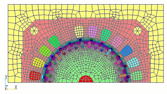
Fig.1 Induction motor 2D mesh model
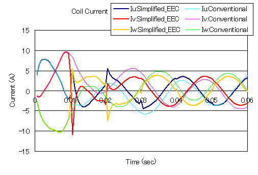
Fig.2 Current variation in stator primary winding with rotation speed 1125rpm at slip S-0.25
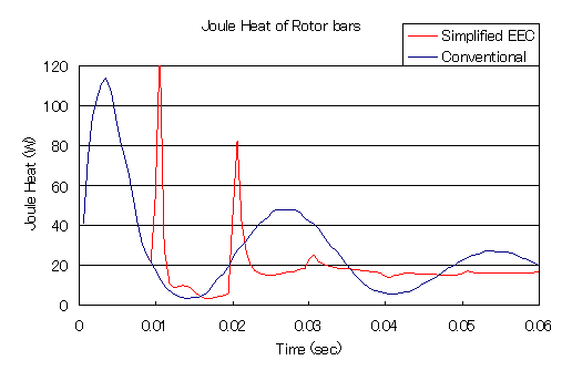
Fig.3 Eddy current loss in rotor bar with rotation speed 1125rpm at slip S=0.25
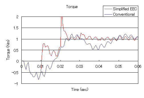
Fig.4 Torque acting on rotor (half) with rotation speed 1125rpm at slip S=0.25
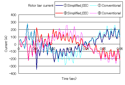
Fig.5 Rotor bar current variation with rotation speed 1125rpm at slip S=0.25
We believe that we have shown that the simplified time-periodic method is effective for the steady-state analysis of induction machines. When applied to induction machines, as explained earlier, this method corrects only for the stator and solves for the armature current and magnetic field in the stator as being semi-periodic. However, since the positional relationship between the stator and rotor bars does not necessarily coincide at each half-period, the solution is not strictly steady-state, although it is fairly close to a steady-state solution. Therefore, we would like you to use the same approach as in the "convergence of the solution to a periodically applied magnetic field", first calculating to a point close to the steady-state solution using the simplified time-periodic method, and then using that as the initial value to restart the analysis to obtain a steady-state solution.
The SD-EEC method cannot analyze a generator or a large field-wound synchronous machine by defining the rotor bars of the cage (short-circuit ring) using SUFCUR, but the simple time-period method can, as shown in the example of the induction machine above.
How to use
Simplified time periodic method is applied by simply entering TP_EEC_OPTION=1 after the SD-EEC time periodic method data in the input file. The analysis can be used only for transient analysis (TRANSIENT) calculations with half periodicity. The settings for the time periodic method are the same as those for "Fast convergence of steady-state solutions of time-periodic problems".
Input Example
Also, as with "Fast convergence of steady-state solutions of time-periodic problems", it is more stable to set THETA and THETA_NETWORK equal to 1, especially when NETWORK is used, and also THETA_MOTION equal to 1 when MOTION is used.
Input Example
Download
- inputNETWORK_Y_S0_25_EEC.txt : Transient analysis by simple EEC method with slip 0.25
- pre_geom2D.neu : Stator mesh data
- rotor_mesh2D.neu : Rotor mesh data
Analysis Examples by Functions
Convergence property improvement and speed-up methods
- Problems with flat tetrahedral elements and their countermeasures
- Node-second-order edge-first-order elements
- Joining hexahedral and tetrahedral elements
- Improved convergence of flat and elongated elements
- Fast convergence to steady-state solutions of time-periodic problems
- Steady-State Analysis of Induction Motors Using a Simplified Time-Periodic Method
- Steady-State Analysis of Rotating Machines by Simplified Multi-Phase AC EEC Method
- Parallel computing capability with OpenMP
- Restart analysis function for changing convergence conditions
©2020 Science Solutions International Laboratory, Inc.
All Rights reserved.