Electromagnetic field analysis software

Electromagnetic field analysis software
Steady-State Analysis of Rotating Machines by Simplified Multi-Phase AC EEC Method
- TOP >
- Analysis Examples by Functions (List) >
- Steady-State Analysis of Rotating Machines by Simplified Multi-Phase AC EEC Method
Summary
In “Fast Convergence of Steady-state Solutions of Time-periodic Problems”, we showed that the TP-EEC method can be applied to stationary and synchronous motors to obtain steady-state solutions at high speed. In “Steady-State Analysis of Induction Motors Using a Simplified Time-Periodic Method”, we showed that the simplified EEC method can be applied to the analysis of induction motors to converge to near steady state at high speed. Here, as an extended version of the simplified EEC method, a fast convergence method for multiphase AC currents is introduced in EMSolution.
Explanation
Multiphase AC is a method that can be applied to more than two phases of AC. The basic idea is based on the simplified EEC method. The simplified EEC method corrects for semi-periodicity by using the relationship $x_0=-x_n$, where $x_0$ is the solution of the equation at a certain point in time and $x_n$ is the value after a half-period in a time step analysis.
As an example, in the case of three-phase alternating current, the equation relating $x_0$ and $x_n$ in three-phase alternating current can be written as follows
$${ x_{0}= \begin{Bmatrix} x_{0}^{1} \\ x_{0}^{2} \\ x_{0}^{3} \\ \end{Bmatrix} = \begin{Bmatrix} x_{n}^{2} \\ x_{n}^{3} \\ -x_{n}^{1} \\ \end{Bmatrix} = \begin{bmatrix} O & I & O \\ O & O & I \\ -I & O & O \\ \end{bmatrix} \begin{Bmatrix} x_{n}^{1} \\ x_{n}^{2} \\ x_{n}^{3} \\ \end{Bmatrix} =Gx_{n} }$$
where the superscript denotes the phase order. Based on the same idea as the simplified EEC method, the correction equation can be expressed as follows
$${ \begin{Bmatrix} p^{1} \\ p^{2} \\ p^{3} \\ \end{Bmatrix} = -\frac{1}{2} \begin{Bmatrix} (x_{0}^{1}+x_{0}^{2}+x_{0}^{3})+(x_{n}^{1}-x_{n}^{2}-x_{n}^{3}) \\ (-x_{0}^{1}+x_{0}^{2}+x_{0}^{3})+(x_{n}^{1}-x_{n}^{2}-x_{n}^{3}) \\ (-x_{0}^{1}-x_{0}^{2}+x_{0}^{3})+(x_{n}^{1}+x_{n}^{2}+x_{n}^{3}) \\ \end{Bmatrix} }$$
From the obtained correction amount $p$, the correction is made as $x_n \leftarrow x_n + p$. This is valid for semi-periodicity, meaning that the correction is made every 1/3 of a half-period step, i.e., three corrections can be made in a half-period. The corrected 3-phase AC has semi-periodicity as shown in Fig. 1. This is three phases with a phase difference of 60 deg. each (=180/3), and the general three-phase AC is represented as the inversion of the second phase (-2). When applied to the stator coil of a rotating machine, it can be applied because U+, W-, and V+ have a phase difference of 60 deg. each. For odd-numbered phases (2$m$ +1) such as 3-phase and 5-phase, the number of phases to be corrected and the actual number of phases match, but for even-numbered phases such as 2-phase and 6-phase, the correction is a little different. The equation can be derived in the same way for 2$m$ phases, allowing for correction.
For example, as shown in Fig. 2, if we want to correct 2 phases in a semi-periodic manner, we are correcting a 4-phase AC that is 90 deg. off. Corrections can be made every half of a half-period. As with the simple EEC method, the multiphase AC simple EEC method does not require solving equations for correction, is simple, and the number of correction times can be increased according to the number of phases.
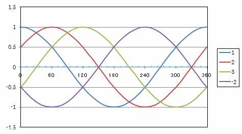
Fig.1 Three-phase AC
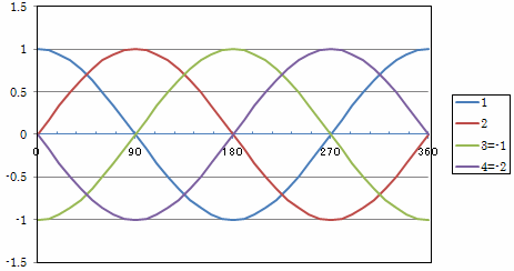
Fig.2 4-phase AC
1. Vrification model
As a simple case, a multiphase AC model is shown in Fig. 3. A coil is fitted into the core and conductors are placed through gaps. The core is made of linear material with a specific permeability of 1000, and the conductors are given appropriate conductivity. In this case, the correction target of the simple multiphase AC EEC method is the coil section. As with the TP-EEC method and the simplified EEC method, it seems to be more stable to set THETA=1 for the time difference.
As a limitation, the mesh of the conductor to be corrected must have the same number of nodes and elements between phases, and the geometry (coordinates) must be periodic.
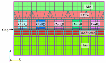
Fig.3 Verification model (5-phase model)
For the analysis, the leftmost phase was used as the reference phase, and calculations were performed by increasing one layer to the right, from 2 to 8 phases. As mentioned earlier, interpolation is performed for phases 2 to 8, so phase 2$m$ is actually phases 4, 8, 12, and 16. The coil currents resulting from the analysis in phases 2, 3, 5, and 8 are shown in Fig. 4. It can be seen that as the number of phases increases, the number of corrections increases, and thus the corrections are made earlier in the process. All phases can be corrected by the simple multiphase EEC method (P-EEC: Polyphase EEC). This shows that the simple polyphase EEC method is very effective.
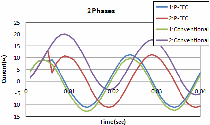
(a) 2 phases
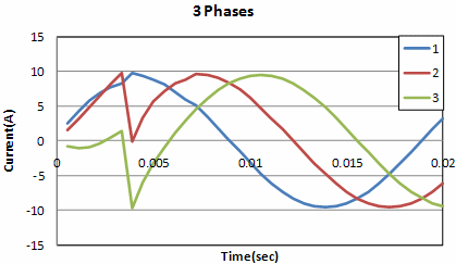
(b) 3 phases
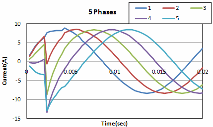
(c) 5 phases
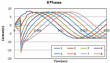
(d) 8 phases
Fig.4 Coil currents by polyphase AC simple EEC method for the validation model
2. Synchronous motor model
As a model of a synchronous motor, we will apply it to the IPM synchronous motor model used in “Fast Convergence to a Steady-State Solutions of Time-Periodic Problems”. However, the model is the two-dimensional model used in “Iron Loss Calculation Using Half-cycle Periodicity” shown in Fig. 5, and it is a sinusoidal voltage source analysis.
Since the conductor as the magnetic field source is the correction target, the current values of the electric circuit connected to the conductor, the iron core, etc. are not corrected, but a correction effect similar to that in the previous example can be expected. In the case of this IPM synchronous motor, since it is semi-periodic at 60 deg. the stator coil has a periodicity of 20 deg.=60/3, the coordinates are shifted every 20 deg. and the number of nodes and elements are assumed to be exactly the same. Fig. 6 compares the results of applying the TP-EEC method (EEC), the Simplified EEC method (S-EEC), and the multiphase AC Simplified EEC method to the stator coil with the calculation without any correction (Conventional).
In this case, the power source frequency of the stator coil is set at 50$Hz$ (0.02sec = 40steps). The TP-EEC method, which allows correction at the same half-period, reaches steady state earlier than the simple EEC method, and the multiphase AC simple EEC method, which allows correction at every 1/3 of a half-period, reaches steady state more quickly. This indicates that the multiphase simple EEC method is more effective. However, since this model is a two-dimensional analysis with no place for (eddy) currents to flow other than the stator coil, the correction effect is more pronounced due to the time constant of the stator coil.
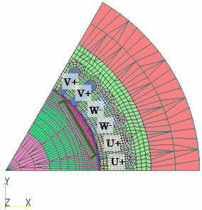
Fig.5 IPM synchronous motor model
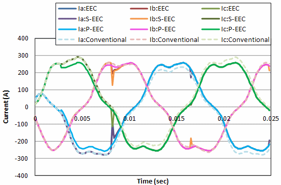
Fig.6 IPM motor steered coil current
3. Induction motor model
Let us apply the multiphase AC simple EEC method to the one-pole model of the induction machine used in “One pole modeling of a squirrel-cage induction motor” shown in Fig. 7. Note that the model with one pole is used because the conductor part to be corrected must be semi-periodic in shape.
A sinusoidal voltage source analysis is performed with slip s=0.25. First, we show the results of applying the three-phase AC simple EEC method to the stator coils compared to the results of applying the simple EEC method to the stator coils.
The power supply period of the stator is set to 50$Hz$ (0.02sec = 36steps). The three-phase AC simple EEC method reaches steady state more quickly because it corrects every 6steps, which is three times more than the simple EEC method which corrects every 18steps.
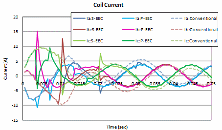
Fig.8 Stator coil current during voltage source analysis
(Induction motor model)
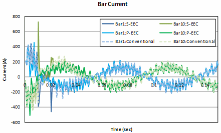
Fig.9 Rotor bar current during voltage source analysis
(Induction motor model)
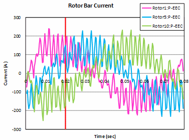
Next, we consider applying the multiphase AC simple EEC method to rotor bars. In general, the number of rotor bars is larger than that of stator coils, so it is possible to correct for more than three phases, and the correction effect is expected. In this case, the current source analysis is performed for the stator coil, and since there are 10 rotor bars, 10-phase correction (20 phases in effect) is possible, so the multiphase AC simple EEC method is applied.
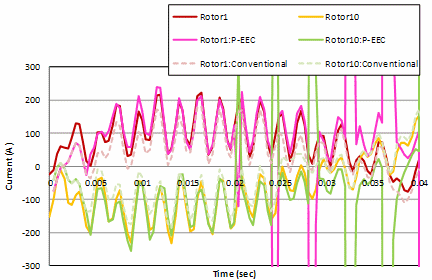
Fig. 10(a) shows the results when slip s = 0.25. The current waveforms of the rotor bars are shown together with the steady-state waveforms obtained by the simple EEC method for the second slip period and those without any correction. The slip period is 12.5$Hz$ (= 0.08 sec), and corrections are made every 1/10 of a half cycle step. Looking at the initial stage of the calculation, the correction is accurate up to about 4 corrections (0.02sec), after which the correction diverges each time.
The current waveforms between rotor bars are not the same between rotor bar phases, even if they reach a steady state. Therefore, if the multiphase AC time-period method, which assumes that the waveforms will be the same between phases by using not only its own phase but also other phases for correction, is used, the correction will be effective and approach steady-state at steps with large low-order errors but will diverge thereafter. When the slip of 0.025 and 0.75 were also calculated, the waveforms diverged as soon as they were corrected for the slip of 0.025, but for the slip of 0.75, as with the slip of 0.25, the first few corrections were possible and then the waveforms tended to diverge (Fig. 11).
When applied to a rotor bar, the ratio (amplitude) of the slot harmonics to the fundamental has a large effect on the correction, and when the slip is small, the fundamental is small and the slot harmonics are on top of the fundamental, so there is no correction effect. In the case of large slip, the fundamental wave is large relative to the slot harmonics, so I think it is effective for the first few times.
When we performed a restart calculation using the result of the fifth correction (at time 0.02sec) as the initial value (Fig. 10(b)), which is corrected accurately at 0.25 slip, a steady state was quickly achieved. When applying the multiphase AC simple EEC method to rotor bars in an induction machine analysis, we recommend that you use this method to accelerate convergence to steady state in the initial stage of the calculation.
Although the multiphase AC simple EEC method may also applied to the rotor bars in stator coil voltage source analysis, since the stator coil current is corrected by the correction effect of the rotor bar, correcting only the rotor bar, which is dependent on the stator coil current, does not seem to be effective.
(a) Comparison with the steady-state value at the initial stage of the calculation
(b) Restart from time 0.02sec
Fig.10 Rotor bar current during current source analysis
(Induction motor model)
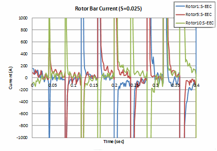
(a) Slip S=0.025
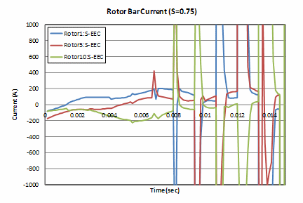
(b) Slip S=0.75
Fig.11 Rotor bar current during current source analysis
(Induction motor model)
From this, we believe we have shown that the multiphase AC simple EEC method is effective. When calculating a large number of steps in a stationary machine or synchronous machine, the multiphase AC simple EEC method may be more effective than the TP-EEC method because it is a simplified method but has a phase-fold correction capability. When applied to an induction machine, it may be possible to quickly converge to a steady-state value with a few corrections in the early stages of the calculation by applying the method to the stator coil in the case of voltage source analysis or to the rotor bar in the case of current source analysis when the slip is rather large.
However, in both cases, as with the simplified EEC method, the positional relationship between the stator and rotor bar does not necessarily coincide every half cycle, so although the solution may be fairly close to the steady-state solution, it is not strictly steady-state. Therefore, we would like you to use the same approach as in the “Convergence of the solutions to periodically applied magnetic fields”, first calculating to a point close to the steady-state solution using the simplified time-periodic method, and then using that as the initial value to restart the analysis to obtain a steady-state solution. I hope you will use it in this way. In the multiphase AC simple EEC method, it is possible to define coils and rotor bars with SUFCUR and analyze them.
How to use
Usage is the same as for the simple EEC method, with the number of half-period correction steps set to N_CORRECT; set TP_EEC_OPTION to a negative value for the number of multiphase ACs; set TP_EEC_OPTION to a positive value for the number of multiphase ACs. Enter the number of properties per phase in the next line NO_MAT_IDS_IN_PHASE, then set the property number per phase. In the example below, the multi-phase AC simple EEC method is applied to the stator coils, so two properties are set for each UVW phase, followed by +U, -V, and +W phases from the top. When setting multiple property numbers per phase, make sure that there is spatial periodicity (mesh) in the order of the property numbers defined for each phase. In the example below, the set properties of 3 phases will be corrected every 6 half-cycle steps. The multiphase AC simple EEC method can be set for both rotors and stators. The analysis can be used only for transient analysis (TRANSIENT) calculations with half-periodicity. The settings for the time-periodic method are the same as in “Fast Convergence to Steady-State Solutions for Time-Periodic Problems”.
Download
- input_90deg_NETWORK_S025_PEECs.ems : Stator coil correction, voltage source analysis
- input_90deg_NETWORK_S025_PEEC.ems : Rotor bar correction, current source analysis
- pre_geom2D.neu : Stator mesh data
- rotor_mesh2D.neu : Rotor mesh data
Analysis Examples by Functions
Convergence property improvement and speed-up methods
- Problems with flat tetrahedral elements and their countermeasures
- Node-second-order edge-first-order elements
- Joining hexahedral and tetrahedral elements
- Improved convergence of flat and elongated elements
- Fast convergence to steady-state solutions of time-periodic problems
- Steady-State Analysis of Induction Motors Using a Simplified Time-Periodic Method
- Steady-State Analysis of Rotating Machines by Simplified Multi-Phase AC EEC Method
- Parallel computing capability with OpenMP
- Restart analysis function for changing convergence conditions
©2020 Science Solutions International Laboratory, Inc.
All Rights reserved.