Electromagnetic field analysis software

Electromagnetic field analysis software
Joining hexahedral and tetrahedral elements
- TOP >
- Analysis Examples by Functions (List) >
- Joining hexahedral and tetrahedral elements
Summary
Traditionally, in order to use hexahedral and tetrahedral elements simultaneously in a single calculation, it was necessary to sandwich a triangular prism element or pyramid element in between them. Pyramid elements are difficult to handle in many general-purpose pre- and postprocessors, and mesh generation tends to be cumbersome. EMSolution allows the joining of hexahedral and tetrahedral elements. As shown in the example below, this has made what used to be a very difficult mesh generation process much easier and more feasible for analysis. Consider the analysis model shown in Fig. 1. A hollow conductor is coiled as shown in the figure, and we consider obtaining the current and spatial magnetic field in the conductor when an AC voltage is applied to both ends. If the wall thickness of the conductor is thicker than the skin depth of the current, it is necessary to mesh the conductor into several layers in the thickness direction.
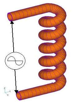
Fig.1 Analysis model
Explanation
Considering the mesh division for such an analysis, it seems appropriate to use hexahedral elements for the conductors as a structural mesh. In fact, the conductor mesh in Fig. 1 was generated by FEMAP. The conductor mesh is generated by defining the conductor centerline and sweeping the cross-sectional mesh partition along the centerline. It is divided into 10 layers in the direction of the wall thickness. At the same time, the mesh in the air region of the pipe is generated in the same way. it would be difficult for a general-purpose mesh generator to automatically divide such a mesh on a tetrahedron. Also, there is a problem of inaccuracy when eddy current analysis is performed using tetrahedral flat elements.
On the other hand, the space around the conductor needs to be divided into a mesh, which is extremely difficult to divide into a structural mesh with hexahedrons. Rather, we would like to automatically divide the space with tetrahedrons. Fig. 2 shows the mesh division of the outer space of a conductor in FEMAP. Here, the surface elements of the conductor are extracted and transformed into triangles, and the triangulated elements of the air domain boundary are added as the perimeter of the air domain, and the interior is automatically divided into tetrahedral meshes.
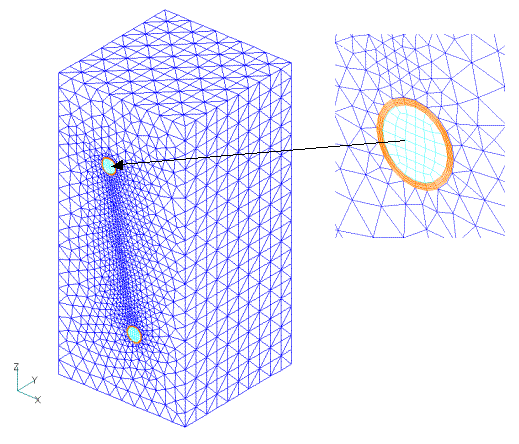
Fig.2 Mesh division of air region
As a result, the conductor and the inside of the pipe are divided into hexahedrons, and the outside air area is divided into tetrahedrons. However, as shown in Fig. 3, two triangles are joined to a quadrilateral surface at the element boundaries, creating floating edges, which are handled appropriately to allow for analysis. Here, it is important to note that the nodes are shared.
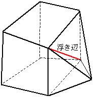
Fig.3 Joining a hexahedron and a tetrahedron
The results of the analysis based on this model are shown below: Figs. 4 and 5 show the current density in the conductor. Fig.6 shows the distribution of magnetic flux density intensity in the cross section.
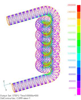
Fig.4 Current density distribution vector diagram
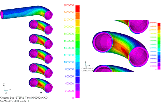
Fig.5 Current density distribution contour diagram
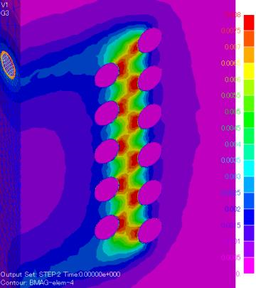
Fig.6 Magnetic flux density distribution contour diagram of cross section
The joining methods shown here can be used universally to join the quadrilateral faces of a hexahedral or triangular prismatic element to the triangular faces of a triangular prismatic or tetrahedral element. However, all are limited to primary elements.
How to use
Simply add QUAD_TRI=1 as shown below. When this option is set to 1, the floating edges as shown in Fig. 3 will be recognized and joined. If there is no floating edge, it is preferable to set QUAD_TRI=0 (or no input). Note that if QUAD_TRI=0 (or no input) even though there is a floating edge, the surface will be considered a far boundary surface.
Download
Analysis model
・ input
・ pre_geom.neu
Analysis Examples by Functions
Convergence property improvement and speed-up methods
- Problems with flat tetrahedral elements and their countermeasures
- Node-second-order edge-first-order elements
- Joining hexahedral and tetrahedral elements
- Improved convergence of flat and elongated elements
- Fast convergence to steady-state solutions of time-periodic problems
- Steady-State Analysis of Induction Motors Using a Simplified Time-Periodic Method
- Steady-State Analysis of Rotating Machines by Simplified Multi-Phase AC EEC Method
- Parallel computing capability with OpenMP
- Restart analysis function for changing convergence conditions
©2020 Science Solutions International Laboratory, Inc.
All Rights reserved.