Electromagnetic field analysis software

Electromagnetic field analysis software
Problems with flat tetrahedral elements and their countermeasures
- TOP >
- Analysis Examples by Functions (List) >
- Problems with flat tetrahedral elements and their countermeasures
Summary
The use of flat tetrahedral elements can cause anomalies, especially in the eddy current density distribution.
Explanation
For example, when a magnetic field is applied to a thin plate conductor as shown in Fig. 2, the eddy currents will be as shown in the figure. The tetrahedron is created by dividing the rectangular body into five tetrahedrons as shown in Fig. 1 (division A). The eddy currents are almost uniform in the thickness direction because the steady-state AC analysis is performed with low frequency. The distribution is wrong for some elements (elements in the center of the rectangular division).
The above results appear in the same way as shown in Fig. 4, even when a rectangular tetrahedron with the same volume is divided (division B) by six tetrahedra as in Fig. 3. This is due to the fact that the elements are flattened, resulting in a larger error.
One solution to this is to use higher-order elements. In EMSolution, we have introduced an edge-first-order node-second-order element (Fig. 5, called a second-order element). If this element is used in the conductor section, reasonable results are obtained even for division A (Fig. 6). Since this element uses a nodal shape function, the analysis must be performed using the A-Φ method. The other is to perform a division (division C) as shown in Fig. 7. In this case, the distribution is reasonable for a first-order element. There does not seem to be much difference between division B and division C. However, in division C, each element has orthogonal three-way edges. Such elements are said to have less error. However, although it is possible to mechanically divide a rectangular body in this way, I think it would be difficult to do so with ordinary meshes. In cases where eddy currents have skin effects, flat elements must be used, and it would be desirable to be able to create such meshes in a mesh generator.
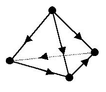
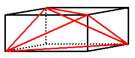
Fig.1 First-order tetrahedral element and division of a rectangular block by tetrahedron (Division A)
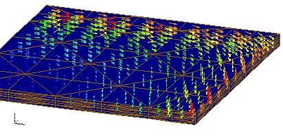
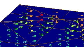
Fig.2 Analysis result of eddy current density distribution in case of Division A

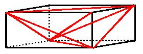
Fig.3 First-order tetrahedral element and division of a rectangular block by tetrahedron (Division B)
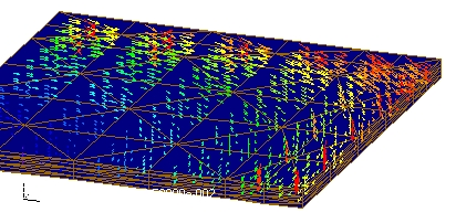
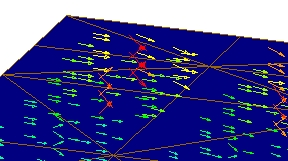
Fig.4 Analysis result of eddy current density distribution by Division B

Fig.5 Second-order tetrahedral element and division of a rectangular block by tetrahedron (Division A)

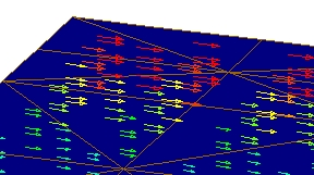
Fig.6 Analysis result of eddy current density distribution by second-order elements in case of Division A
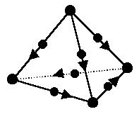
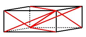
Fig.7 Second-order tetrahedral element and division of a rectangular block by tetrahedron (Division C)
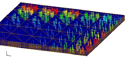
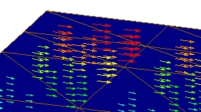
Fig.8 Analysis result of eddy current density by secondary elements in case of Division C
Download
Block Model
First-order element, Division A
・ input1
・ pre_geom.neu
First-order element, Division B
・ input2
・ pre_geom.neu
Analysis Examples by Functions
Convergence property improvement and speed-up methods
- Problems with flat tetrahedral elements and their countermeasures
- Node-second-order edge-first-order elements
- Joining hexahedral and tetrahedral elements
- Improved convergence of flat and elongated elements
- Fast convergence to steady-state solutions of time-periodic problems
- Steady-State Analysis of Induction Motors Using a Simplified Time-Periodic Method
- Steady-State Analysis of Rotating Machines by Simplified Multi-Phase AC EEC Method
- Parallel computing capability with OpenMP
- Restart analysis function for changing convergence conditions
©2020 Science Solutions International Laboratory, Inc.
All Rights reserved.