Electromagnetic field analysis software

Electromagnetic field analysis software
Handling of Rotor Bars and End Rings in Two-Dimensional Analysis of Squirrel-cage Induction Motors
- TOP >
- Analysis Examples by Functions (List) >
- Handling of Rotor Bars and End Rings in Two-Dimensional Analysis of Squirrel-cage Induction Motors
Summary
In the magnetic field analysis of a squirrel-cage induction machine (induction motor), a three-dimensional model is considered necessary to properly model the rotor bars and end rings in the rotor (conceptual diagram Fig. 1). However, since 3D analysis requires a large amount of computation time and induction motors generally reach a steady state very slowly, 2D analysis that does not take into account the effects of the end rings is often used. An example of induction motor analysis by using EMSolution has already been shown in "Induction Motor Analysis". There, the end rings are not included in the analysis and their effects (mainly due to resistance) are approximated by reducing the conductivity of the rotor bars. In this case, the area-integrated axial current in the rotor bar should be zero, so SUFCUR (Surface Inflow Current Source) is used to set the total axial current area-integrated value to zero. In the case of a two-dimensional analysis, the axial current integral value will generally not be zero unless such a constraint condition is put in place.
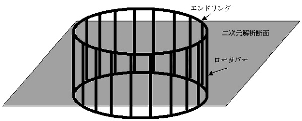
Fig.1 Rotor bars and end rings of squirrel-cage induction machine
Explanation
A more realistic approximation method for two-dimensional analysis is to simulate an end ring with a resistor and incorporate it into an electric circuit, coupling it with the finite element method. Fig. 2 shows the equivalent circuit. The rectangles in the finite element analysis area surrounded by dotted lines represents a rotor bar.
The resistors represent end rings, which connect the rotor bars adjacent to each other at the top and bottom. Assuming that the rotor bars are equally spaced, the resistance values are all equal. In addition, it is possible to add resistance at the ends of the rotor bars or to insert inductance to include inductive effects, but for simplicity, we will only deal with resistance values here. Also, since the same current flows in the upper and lower sections, the lower section can be connected with zero resistance between the nodes (black circles in Fig. 2) and the upper section’s resistance can be doubled. An electrical circuit like the one in Fig. 2 can be easily created using the NETWORK module and can be coupled with the finite element method. For a 360-degree model without rotational period symmetry, it is sufficient to consider all rotor bars and end rings as shown in Fig. 2, but in many cases there is symmetry. The analysis can be performed by modeling only the periodic part (the mesh part).
As an example, let’s assume an N-fold symmetrical model with N series circuits on the primary side and model it for 1/N. If REGION_FACTOR=N, the primary input voltage and coil resistance can be set as a full cycle model. In this case, set the end ring resistance as N times so that the secondary currents flowing in the rotor bar and end ring are the same as in the full circumference model、so the resulting currents are equal to the primary and secondary currents flowing in the full circumference model. If REGION_FACTOR=1, the end ring resistance can be set as the full circumference model, but the primary input voltage and coil resistance must be set to 1/ N to make the resulting current equal to the primary and secondary current values flowing in the full circumference model. In this case, CURRENT for SUFCUR can be set to 1 in both cases.
Fig. 4 shows an example of a finite element mesh in which the end rings are approximated as resistance in the model used in "Induction Motor Analysis". The rotor bars of the rotor must all have different property numbers. The rotor bars on the periodically symmetric surface are rotationally symmetric, so the same property numbers are set for them. In "Induction Motor Analysis", the power circuit is entered using CIRCUIT and the conductivity of the rotor bars is set to take into account the effect of end rings, as described above. In this example, NETWORK is used here instead of CIRCUIT, and NETWORK allows the resistance of the end rings to be set separately.
To set up a three-phase AC power supply, you can also set up the circuits for the three phases independently, but here we consider a Y-shaped connection. When using CIRCUIT to set up, CONNECTION_MATRIX must be entered, which is not easy to set up intuitively. NETWORK can be used to set up the actual power circuit as it is. In this example, the Y-connection is made so that the voltage between phases is $100 \sqrt 3V$ (RMS value). If a current power input is used, the neutral point must be connected with a large resistor. In "Induction Motor Analysis", Delta-connection is used so that the voltage between phases is 100 V (RMS value). See "Delta and Y-connection" for an example of the wiring method and input, as well as some precautions for wiring a three-phase AC power supply.
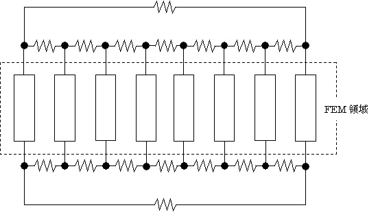
Fig.2 Equivalent circuit of rotor bars and end rings of rotor
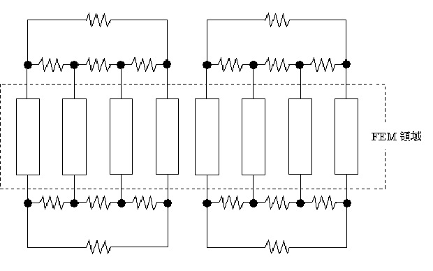
Fig.3 Equivalent circuit in the case with periodic symmetry
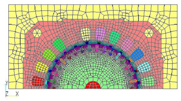
(a) Overall viewル
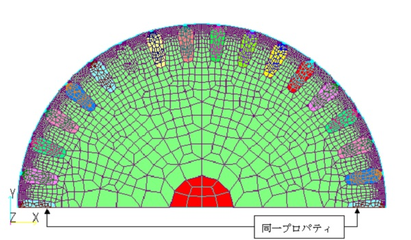
(b) Enlarged view of rotor section
Fig.4 Analytical mesh considering end rings by using NETWORK
The current and torque waveforms of the stator primary winding obtained from the analysis at slip S = 0.25 are shown in Figs. 5 and 6. It can be seen that this model is in good agreement with the results obtained by correcting the conductivity of the rotor bars in "Induction Motor Analysis". Fig. 7 shows the current waveform of the rotor bar for the property number shown in Fig. 4, and Fig. 8 shows the end ring current waveform connected to the rotor bar in Fig. 4.
In this way, the currents flowing in each rotor bar and the current waveforms of the end rings can be seen even in the two-dimensional analysis.
In reality, it is difficult to determine the resistance of the end ring in general, since it is considered to be frequency dependent due to skin effects and also depends on the shape of the end ring. Rather, it may be realistic to adjust the resistance value to better match the experimental results.
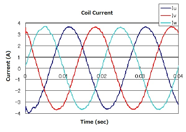
Fig.5 Current variation in stator primary winding at slip S=0.25
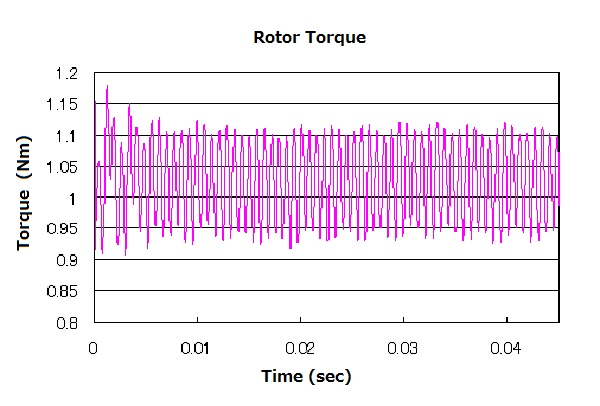
Fig.6 Torque acting on the rotor (half) at slip S=0.25
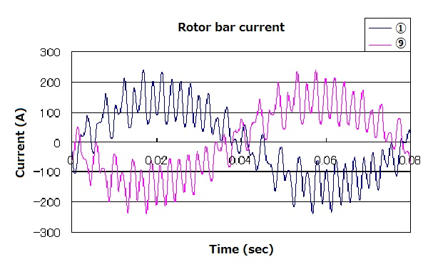
Fig.7 Rotor bar current variation at slip S=0.25
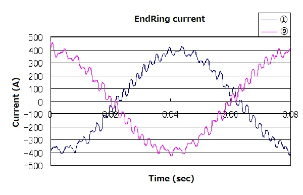
Fig.8 End ring current variation at slip S=0.25, speed =1125 rpm
How to use
- In Handbook “16.1 Volume Element Properties," set the conductivity to the rotor bar property. Here, the conductivity of aluminum is set as it is.
-
Set the rotor bar in Handbook "17.5 Surface Inflow Current Source (SUFCUR)".
-
In Handbook "17.8 Power Supply and Wiring (NETWORK)", connect the rotor bars set in 2 with resistors that simulate end rings. Also set up a three-phase AC power supply; since this is a 180-degree model, set REGION_FACTOR=2, which doubles the resistance of the end rings. The resistance of the end ring is $10.50 \mu \Omega$, calculated from the dimensions with reference to Reference [1].
References
[1] "Electromagnetic Field Analysis Techniques for Virtual Engineering of Rotating Machines," IEEJ Technical Report No. 776 (2000/3)
Download
Analysis Model
・ inputNETWORK_Y_AC.ems : AC steady-state analysis
・ inputNETWORK_Y_1125rpm.ems : Transient analysis
・ pre_geom2D.neu : Stator mesh file
・ rotor_mesh2D : Rotor mesh file
Analysis Examples by Functions
Induction motor analysis
©2020 Science Solutions International Laboratory, Inc.
All Rights reserved.