Electromagnetic field analysis software

Electromagnetic field analysis software
Definition of COIL
(external current field source)
by hexahedral element mesh
- TOP >
- Analysis Examples by Functions (List) >
- Definition of COIL (external current field source) by hexahedral element mesh
Summary
In EMSolution, COIL can be created and defined as a hexahedral mesh. Hereafter, COIL defined by a mesh is referred to as Meshed COIL.
Explanation
Application to modelling of helical coils
The model shown in Fig. 1 is created as follows: First, a quadrilateral coil cross-sectional shape is created. Next, it is extruded along the length of the coil to create a hexahedral element.
The cross section does not necessarily have to be rectangular and can be distorted. However, the four nodes on the bottom and top surfaces of the hexahedral element must be in one plane. If the upper and lower surfaces are not on one plane, the calculation can still be performed, but strictly speaking, current continuity may not be satisfied. The mesh defined in this way is stored in the file "COIL_geom.xxx" as an input file. The .xxx extension depends on the INPUT_MESH_FILE in "input. 10. input/output file”. If the geometry can be expressed by ARC or GCE, it is better to use them to obtain a more accurate solution since they are calculated analytically.
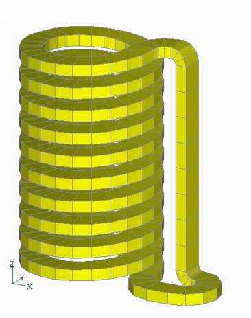
Fig.1 COIL (Meshed_COIL) definition with hexahedral element mesh
Fig.2 and 3 show the magnetic field on the center plane obtained by current integration. The definition of Meshed COIL is described in the definition of COIL as well as GCE, ARC, etc. When CALC_IND is set to 1, the inductance is calculated and included in the circuit calculation. The results of the electromagnetic force calculation for COIL are shown in Fig. 4. Although only the self-force of COIL is calculated in this calculation, electromagnetic force calculations that include the contribution of conductors and magnetic materials are also possible by combining the finite element method.
For inductance and electromagnetic force calculations, you can specify the number of Gaussian integration points in the element cross section (NX, NY) and Gaussian integration points in the current direction (NZ). Setting NZ=0 performs an adaptive calculation that automatically determines the number of integrals in the current direction. Table I shows the results of inductance calculations with these parameters. In this example, NX=NY=NZ=3 seems to be sufficient. As the number of hexahedral elements increases, the computation time increases (the computation time for inductance is proportional to the square of the number of elements). In addition, when used as a magnetic field source in a reduced potential region, integration at the boundary surface is required, which can be very time-consuming. This problem can be avoided by using the restart function. Since this calculation and inductance calculations are performed in the MAKE_SYSTEM_MATRICES process, it is possible to calculate the inductance first, and enter the inductance as a circuit constant in NETWORK or CIRCUIT and then to make calculation with the CALC_IND option set to 0. (This saves calculation time.)
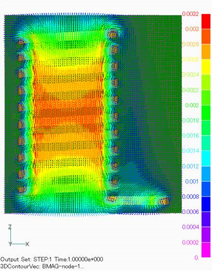
Fig.2 Magnetic flux density distribution arrow diagram
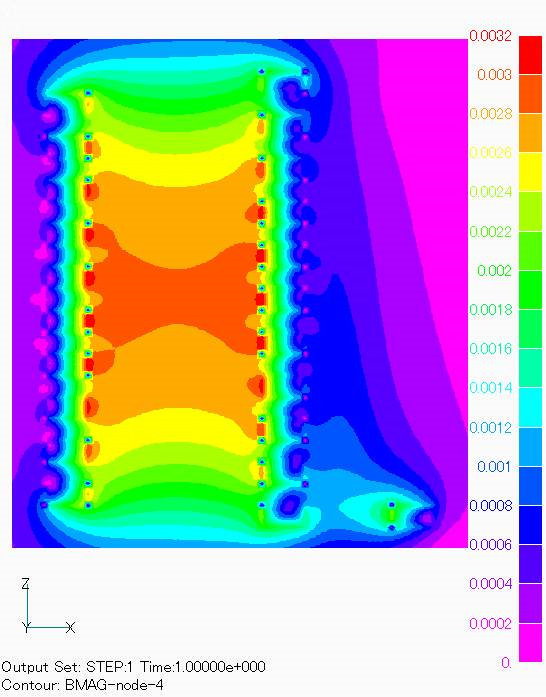
Fig.3 Magnetic flux density intensity contour diagram
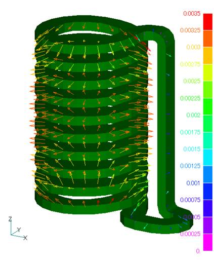
Fig.4 COIL electromagnetic force distribution
Table I. Inductance Calculation
| Nx | Ny | Nz | CPU Times ( s ) | Inductance( μH ) |
| 3 | 3 | 3 | 95.3 | 7.31916 |
| 5 | 5 | 5 | 452.7 | 7.31831 |
| 7 | 7 | 7 | 1218.5 | 7.31815 |
| 3 | 3 | 0 | 240.7 | 7.31875 |
Application to rotating machine windings
The following is an example of using Meshed COIL for the stator winding of a rotating machine (permanent magnet motor).
Fig. 5 shows the whole shape of the defined coil. One coil is created, rotated and copied to make 12 coils, and each phase is given a property number. Since this analysis uses top-bottom symmetry and 4-fold periodic symmetry, the integral region is defined only in the 1/8 region for the inductance calculation, and the integral region is defined separately as shown in Fig. 6. The Meshed COIL defined in this way must be defined within the reduced potential region, just like a conventional COIL. This is shown in Fig. 7. The reduced potential region is defined as the region covering the coil slot and the coil end portion.
The torque waveforms analyzed by Meshed COIL are shown in Fig. 8. The results are superimposed on the results of other modeling (Fig. 11 of "Application of COIL to Motor Winding"). Note that the coil end portion shown in Fig. 5 was created virtually; in reality, it must be modeled according to the real equipment.
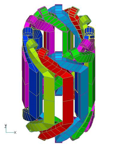
Fig.5 Mesh model of stator winding
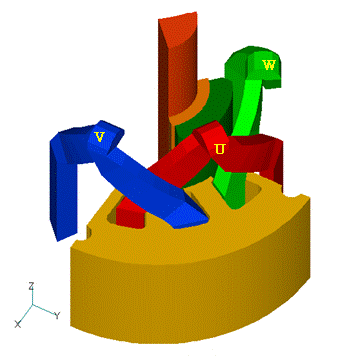
Fig.6 Mesh model of stator winding (integral elements)
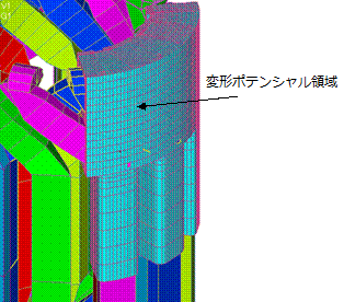
Fig.7 Mesh model of stator winding and reduced potential region
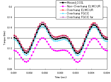
Fig.8 Torque analysis results
(1/2 region)
How to use
COIL mesh definition
Define a COIL mesh and name the file COIL_geom.xxx. The extension xxx matches the format set in "input 10. input/output file INPUT_MESH_FILE." COIL_geom contains node and element data. Elements are given different properties (property numbers) for each COIL. Each element of the Meshed COIL is represented by a hexahedron (Fig. 9). The direction of the current is from the bottom (1-2-3-4) to the top (5-6-7-8). The bottom and top surfaces do not necessarily have to be rectangular, but they must lie on one plane.
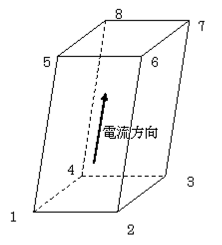
Fig.9 Meshed_COIL element
Starting from r10.4.1, the current direction defined in Meshed COIL is output. The current density (density of turns) when a current of 1A flows is output to the COIL_current file (e.g. current density distribution of Meshed COIL in Fig. 1) The COIL_current file is automatically output if Meshed COIL is used. Use it for confirmation purposes.
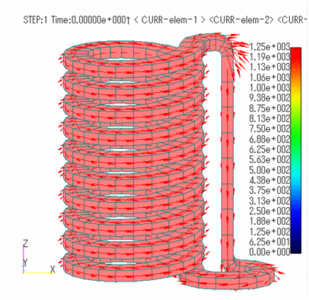
Fig.10 Current density distribution of Meshed_COIL
(for confirmation)
input file
In the "17.1. External Current Field Source (COIL)" setting, use MESH as the title to correspond to the property number in COIL_geom. CURRENT is the amount of current (A) when the current direction in Fig. 9 is positive. MESH-ID corresponds to the property number in COIL_geom. In the mesh data defined as one COIL series, current must be closed. MESH- is an element for integrating inductance and electromagnetic force and is required when calculating inductance and electromagnetic force. For MESH-, the number of divisions (NDIV) and the number of Gaussian integration points (NX, NY, NZ) must be entered. NX, NY, and NZ are the same as for GCE- and ARC-.
To calculate the coil inductance, set the CALC_IND option of "4. Order of the shape function" to 1.
To calculate the electromagnetic force of COIL, set COIL_FORCE=1 in "10. Input/Output File". If COIL_FORCE=1, the electromagnetic force of GCE- and ARC- is output to output.
As for MESH-, in addition to output to output, it also outputs to COIL_FORCE file. The file format is set in POST_DATA_FILE in "10. Input/Output File". In this case, the data in "11.4. Spatial Magnetic Field by Magnetization and Current Integration” must be entered.
Download
helical coil
・ inputHelical
・ COIL_geom.neu :Meshed COIL file
・ B_integ_mesh.neu :Spatial integral mesh file
PM motor
・ input_PMMotor
・ COIL_geom.neu :Meshed COIL file
・ pre_geom2D.neu :Mesh file (stator)
・ rotor_mesh2D.neu :Mesh file (rotor)
・ 2D_to_3D :3D extension file
Analysis Examples by Functions
External current magnetic field source
- About the multi-potential method
- Definition of COIL (external current field source) by hexahedral element mesh
- Magnetic field distribution calculation in a COIL-only model
- Circuit calculation with COIL (external current field source) only
- COIL inductance and electromagnetic force calculations
- Inductance Calculation for COIL (external current magnetic field source)
- Handling of inductance in external current field source (COIL)
- About COIL Move
- Problems with external magnetic field current sources in the case of translational periodicity
- Notes on the use of GCE (rectangular current element)
©2020 Science Solutions International Laboratory, Inc.
All Rights reserved.