Electromagnetic field analysis software

Electromagnetic field analysis software
Analysis using SUFCUR
(Surface Current Source)
- TOP >
- Analysis Examples by Functions (List) >
- Analysis using SUFCUR
(Surface Current Source)
Summary
Surface current source (SUFCUR) simulates the case where a voltage is applied to a certain surface of a bulk conductor and current flows through it.
Explanation
When current flows in a bulk conductor, skin effects appear, and the current density distribution in the conductor changes with frequency, resulting in a change in its impedance when viewed as a coil. Here the analysis is performed by considering the coil used in the explanation of "Static magnetic field analysis using ELMCUR (element current source)"as a one-turn bulk conductor. In this case, the inflow and outflow surfaces are different and are on the Bn=0 surfaces, but the case of a closed loop with the same inflow and outflow surfaces will be discussed in "Surface Current Source in a Closed Loop (SUFCUR)" of "Analysis Using Gap Elements" section.
First, the surface on which the current flows in (the plane to which the positive voltage of the power supply is applied) must be specified. Let us assume that it is the surface A in Fig. 1. The surface where the current flows out is the surface B. Considering the symmetrical parts, the current path goes around. Surfaces A and B must be defined as Bn=0 surfaces. A surface element is defined on the surface A, where the property number is 14. The orientation of the surface can be in either direction in case of SUFCUR, but we will define it to face outward (right-hand thread) from the conductor in order to share it with the surface for calculating the passing current. In the current case, surface A is still created by extending from the line element in the z direction. Sample data for this is prepared in pre_geom2D.neu and 2D_to_3D. Specify the coil area, inflow surface, etc. in the input file. Here, A-ϕ is used because it converges faster than the A method. For low frequencies or when SUFCUR is used, the convergence of the ICCG method is better.
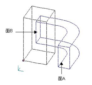
Fig.1 Surface inflow current source plane
A portion of the output file output is shown in List.1.
As in "the "ELMCUR analysis", the impedance of the coil from the power supply can be obtained as
$$R + j \omega L = \frac{(0.0476377 + j0.110901)}{3000}(\Omega) = 15.88 + j 36.97(\mu \Omega)$$
but there is a resistance of 5 μΩ added in series with the coil, so the impedance of the coil itself (including the effect of eddy currents in the copper conductor) is $10.88+j36.97(\mu \Omega)$. In order to compare with the result in "AC analysis including eddy currents", the result is converted to 3000Turn equivalent (3000 squared times) values, then it is $97.9+j332(\Omega)$. Due to the skin effect, the resistance is larger and the inductance component is smaller. Also, since this is a one-eighth model, the overall average heat generation is $6.1196×8=48.95W$.
This value should be equal to the heat generation obtained from the above resistance value: $\frac{(I^2×R)}{2}=\frac{(3000^2×10.88×10^{-6})}{2}=48.96W$. The values are in fact almost the same, indicating that the solution is consistent. The surface passing current value is equal to half of the coil current as set. The sign is different because the direction of the surface is opposite. (The surface of passing current must be defined outward from the conductor.) Fig. 2 shows the current density distribution at phase 0 degrees. Fig. 3 shows the heat generation density distribution. It can be seen that the distribution of coil current and heat generation is inward (larger on the inside).
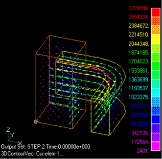
Fig.2 Current density distribution
(phase 0 degree)
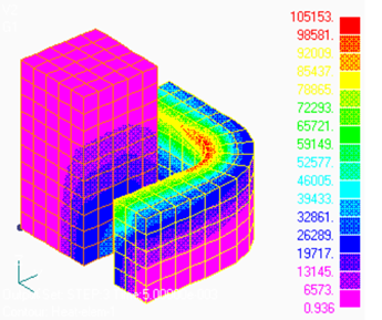
Fig.3 Heat generation
density distribution
((phase 0 degrees, $W/m^3$)
How to use
Let the surface element with property number 14 be the inflow surface; CURRENT=0.5 means that 0.5 current passes through the surface for every 1 supply current.
Download
・ input :Input condition file
・ pre_geom2D.neu :Mesh file
・ 2D_to_3D :2D mesh extension file
©2020 Science Solutions International Laboratory, Inc.
All Rights reserved.