Electromagnetic field analysis software

Electromagnetic field analysis software
Surface inflow current source in a closed loop (SUFCUR)
- TOP >
- Analysis Examples by Functions (List) >
- Surface inflow current source in a closed loop (SUFCUR)
Summary
When using SUFCUR as a bulk conductor surface inflow source, if there is a $B_n$=0 symmetry condition, defining a face element on one $B_n$=0 face makes that face the positive electrode and the other $B_n$=0 face the negative electrode and current flows out. When there is no such symmetry condition and current is induced by applying a voltage to the loop conductor, a gap element is used.
Explanation
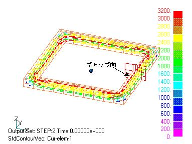
Fig.1 Surface current inflow source in a closed loop bulk conductor
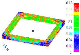
Fig.2 Heat generation density distribution
When a gap element is specified, electrical potentials are defined on both sides of it. If you define a SUFCUR surface to overlap that surface, a positive potential is defined on the positive side of the gap (in the right-hand thread direction of the element) and the negative side is set to zero.
Suppose we have a closed loop conductor as shown in Fig. 1. In this case we can use the symmetry condition, but we will solve for the entire upper half. Define a gap surface as shown in the figure. Gap surface elements can also be used as SUFCUR definition elements. First, create a mesh by extending in the z-direction from pre_geom2D.neu and 2D_to_3D, define the gap surface and SUFCUR surface with input, and perform an AC steady-state analysis. The loop current is induced as shown in Fig. 1, and the heat generation distribution is shown in Fig. 2.
Here we have shown the case where SUFCUR is defined on a symmetrical surface, but it can also be defined in an asymmetrical position. It can also be used in combination with a gap element on one end face, even when using rotational symmetry. $\Rightarrow$ "SUFCUR at asymmetric locations or periodic boundaries".
How to use
Set the gap surface and SUFCUR definition surface to serve as a dual-use surface.
Download
・ input2D
・ pre_geom2D.neu
・ 2D_to_3D
©2020 Science Solutions International Laboratory, Inc.
All Rights reserved.