Electromagnetic field analysis software

Electromagnetic field analysis software
Current Field Analysis on Periodic Boundaries
- TOP >
- Analysis Examples by Functions (List) >
- Current Field Analysis on Periodic Boundaries
Summary
When defining "PHICOIL", "SUFCUR" and "DCCURR" as coils and bulk conductors across a periodic boundary surface, it was previously necessary to define gap elements on the coil or conductor cross section inside the mesh. This was no longer possible when defining a current inflow surface at the periodic boundary with a gap element. We are pleased to report that it is now possible to define the current inflow surface on the periodic boundary without gap elements. The analysis can also be performed for steady-state current field analysis.
Explanation
This function is a type of periodic boundary condition, also called an equidifferential periodic boundary condition (Ref. [1]). To provide a potential difference between periodic boundaries, a gap element was used to provide a potential difference as in the 360-degree model, but now it can be solved by providing a potential difference between the current inflow and outflow surfaces. This allows the "PHICOIL at periodic boundaries" and "PHICOIL in rotational z-anti-mirroring symmetry" models to be analyzed without gap elements at the periodic boundaries.
■ PHICOIL at periodic boundaries (without gap element)
As a validation calculation, we use the model of "PHICOIL at the periodic boundaries" to define a PHICOIL current input surface at the periodic boundaries.
Fig. 1 shows the calculation results together with the results defined using gap elements inside the mesh. It can be seen that the results are in agreement, as expected. Although the gap element must be defined one layer beyond the coil cross section, it is now possible to define the current input surface only on the coil cross section as well as the mirror symmetry surface on the periodic boundary plane, which simplifies the setup.
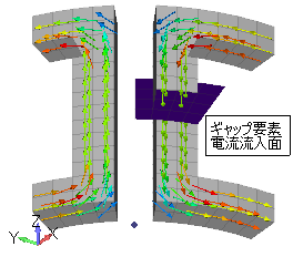
(a) Gap Element Definition
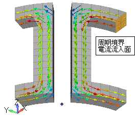
(b) Periodic boundary surface definition
Fig.1 Current density vector distribution $[A/m^2]$
■ Periodic boundary conditions in steady-state current field analysis
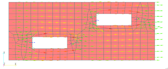
Consider the model shown in Fig. 2, in which the conductor with holes is modeled with periodic boundaries, and a steady-state current field analysis[1] is performed. Assume that the periodic boundary condition is satisfied in the x-direction and that current continuity is satisfied. In this case, the use of periodic boundary conditions means that a part of the analytical model is taken out, so the voltage applied to both ends of the model is input. If the model is a 1/10 model, the analysis can also be done by inputting the voltage across the entire model and setting REGION_FACTOR=10.
Fig. 3 shows the current distribution obtained for the periodic boundary condition and the mirror symmetry condition. In the case of the mirror symmetry condition, the current flows in and out perpendicularly at the boundary, whereas in the periodic boundary condition, the current density has oblique components on both sides. In this model, there is only a slight difference, but depending on the problem, the difference may not be negligible, so we hope you will use this function.

Fig.2 Model of conductor with holes

(a) Mirror symmetry condition
(b) Isoperiodic boundary condition
Fig.3 Current density vector distribution $[A/m^2]$
Briefly, we have introduced a function that allows the analysis of periodic boundaries using PHICOIL and steady-state current field analysis without gap elements. As mentioned earlier, this function can be used with "PHICOIL", "SUFCUR", "DCCURR" and "Steady Current Field Analysis Function". As with the mirror symmetry surface (Bn=0 surface), a current input surface can be defined as the periodic boundary surface.
References
[1]: Tokumasu, Fujita: "Remaining issues in two-dimensional analysis," Joint Research Institute of Electrostatic Stator and Rotating Machinery, SA-05-73, RM-05-80 (2005)
How to use
■ PHICOIL at periodic boundaries (without gap element)
Define PHICOIL (Handbook "17.4 Potential Current Sources"). Define a periodic boundary current inflow surface for SMAT_ID_IN.
■ Periodic boundary condition in steady-state current field analysis (isoperiodic boundary condition)
Define periodic boundary conditions (Handbook "14. Periodic Boundary Conditions, Sliding Surfaces").
Download
■ PHICOIL at periodic boundaries
・ input_gap_element.ems :gap element definition
・ input_periodic_boundary_surface.ems :Periodic boundary surface definition
・ pre_geom2D.neu :Mesh file
■ Periodic boundary conditions in steady-state current field analysis
・ input_Mirror.ems :Mirror surface boundary
・ input_periodic_boundary_surface.ems :Periodic boundary
・ pre_geom2D.neu :Mesh file
Analysis Examples by Functions
Current magnetic field source
- PHICOIL in rotational z-anti-mirroring symmetry
- Loop current defined by Potential Current Source (PHICOIL)
- PHICOIL at periodic boundaries
- SDEFCOIL and PHICOIL
- Steady-state DC+AC analysis of bulk conductors using PHICOIL and SUFCUR
- Heat generation output of current magnetic field sources
- DC current field analysis of bulk conductors
- Current Field Analysis on Periodic Boundaries
©2020 Science Solutions International Laboratory, Inc.
All Rights reserved.