Electromagnetic field analysis software

Electromagnetic field analysis software
DC current field analysis of bulk conductors
- TOP >
- Analysis Examples by Functions (List) >
- DC current field analysis of bulk conductors
Summary
For analysis of bulk conductors, including eddy currents, "SUFCUR" is available. However, SUFCUR cannot be used in static magnetic field analysis (STATIC). For STATIC, "PHICOIL" can be used as a similar function, but it is designed for coils and cannot be applied to conductors in contact with members with different conductivities. We now introduce DCCURR, a current field source that extends PHICOIL. DCCURR performs calculations similar to steady-state current field analysis and uses the current distribution as the input current distribution, similar to PHICOIL. The current distribution calculation functionality is the same as that of "Steady Current Field Analysis". However, DCCURR can calculate the magnetic field distribution by current distribution and output Joule loss and resistance.
Explanation
The model shown in Fig. 1, which simulates a conductor with two branches, is used in the analysis. The two branches have the same geometry, but the conductivity of one side is halved. This is equivalent to doubling the resistance. A DC current of 90 A is applied to the lower surface before the bifurcation as the input current for analysis. Fig. 2 shows the current distribution. If only conductors are analyzed, the "Steady Current Field Analysis" function can also be used. It can be confirmed that the current distribution is biased. Calculating the amount of current passing through the branch using the "Passing Current Calculation Surface" function, it can be confirmed that the current passes through the conductor at a ratio of approximately 1:2 (Table 1).
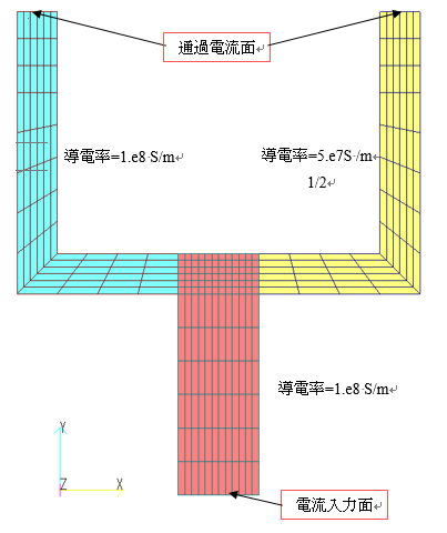
Fig.1 Bifurcated conductor model
(excluding air region)
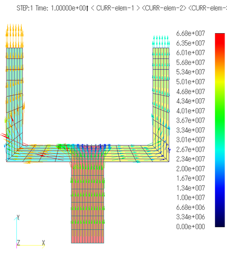
Fig.2 Current density vector distribution ($A/m^2$)
Table 1 Pass-through current and heat generation
| Right Branch | Left Branch | |
| Currency current amount | 30.66 $A$ | 59.34 $A$ |
| calorific value | 0.175 $W$ | 0.328 $W$ |
| resistance | 1.86e4 $Ω$ | 0.931e4 $Ω$ |
The amount of heat generation can be output for each part in the series for each series as shown below using the "Heat generation value output for magnetic field source" function. If you want to calculate the resistance for each area, you can use the heat generation value $Q$ for each area to calculate $R=Q/I^2$. Fig. 4 shows the magnetic flux density distribution due to conductor current.
Output of Heat Generation
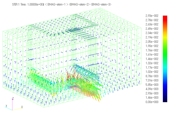
Fig.3 Magnetic flux density vector distribution [T]
*Property surface only
Briefly, we introduced the DC current field analysis of bulk conductors. This function can be used to obtain the DC current distribution of a bulk conductor and the resulting magnetic field distribution. It can also be used as an initial value for transient analysis involving eddy currents in conductors. In this case, the current field source is set to "SUFCUR" and the element properties must be set as conductors.
How to use
Define "DCCURR" as the current field source as follows
You can set as many conductors as you set in NO_PARTS, where MAT_ID is the solid conductor property, SMAT_ID is the current input surface, CURRENT is the normalized current amount, and SIGMA is the conductivity. For the second and subsequent conductors, only MAT_ID and SIGMA can be set. SIGMA must be set. Input current should be set in CIRCUIT or NETWORK. If there are two or more independent conductors, define multiple DCCURRs. By setting HEAT=1, the heat value and heat density for each element are output in the HEAT file and the heat value in the OUTPUT file.
Download
・ input3D_DCCURR.ems
・ inputRestart3D_SUFCUR.ems
・ pre_geom2D.neu :Mesh file
・ 2D_to_3D :2D mesh extension file
Analysis Examples by Functions
Current magnetic field source
- PHICOIL in rotational z-anti-mirroring symmetry
- Loop current defined by Potential Current Source (PHICOIL)
- PHICOIL at periodic boundaries
- SDEFCOIL and PHICOIL
- Steady-state DC+AC analysis of bulk conductors using PHICOIL and SUFCUR
- Heat generation output of current magnetic field sources
- DC current field analysis of bulk conductors
- Current Field Analysis on Periodic Boundaries
©2020 Science Solutions International Laboratory, Inc.
All Rights reserved.