Electromagnetic field analysis software

Electromagnetic field analysis software
SDEFCOILとPHICOIL
- TOP >
- Analysis Examples by Functions (List) >
- SDEFCOIL and PHICOIL
Summary
EMSolution provides "surface-defined current sources (SDEFCOIL)" and "potential current sources (PHICOIL)" as current sources. They are functionally very similar, and an example will be used here to illustrate the differences.
Explanation
The magnetic field produced by a circular coil (average radius 1.5 m, rectangular cross section 1 m) is analyzed in a 1/4 domain model as shown in Fig. 1. The element partitioning is a tetrahedral unstructured mesh; EMSolution also has a current source input method using ELMCUR (internal current source), but it cannot be used for such an unstructured mesh. Possible input methods are SDEFCOIL and PHICOIL.
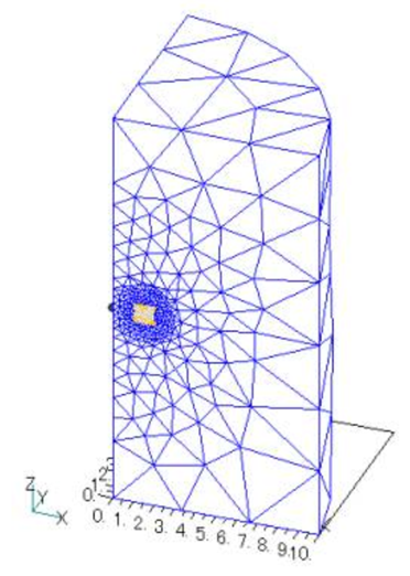
Fig.1 Analysis mesh
First, to set up the coil, SDEFCOIL defines four planes (1),(2),(3), and (4) surrounding the current path shown in Fig. 2 using surface elements. Each surface element has a different property number and is defined with the inside of the coil as the positive direction of the face, in the order of the right-hand thread direction relative to the current direction. On the other hand, PHICOIL defines the current inflow surface (5). The current outflow plane is assumed to be the opposite symmetry plane and does not need to be defined. When the coil is closed, as in the full circumference model, a gap element is used together.
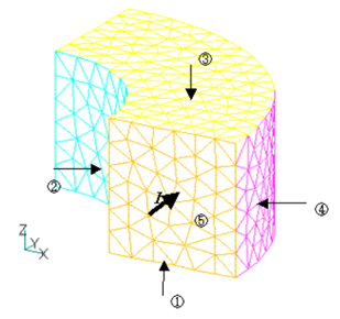
Fig.2 Coil surface mesh
In SDEFCOIL, the current distribution is obtained from the following formula given a potential φ that varies from 0 to 1 between planes (1) and (3) and a potential ψ that varies from 0 to 1 between planes (2) and (4):
$$J=I\nabla\phi×\nabla\psi$$
Potentials $φ$ and $ψ$ are given geometrically by the ratio of distances from the surfaces. On the other hand, in PHICOIL a constant electric potential φ at surface (5) is given and the potential is solved as a steady current field problem, and the current density is calculated from
$$J=-\alpha\phi$$
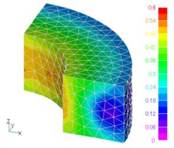
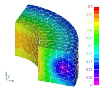
where $α$ is determined so that the total current in the coil is $I$. In fact, if we calculate the current density for both, the current density will be as shown in Fig. 3. For SDEFCOIL, the current density is almost uniform (1$MA$/$m^2$). In the case of PHICOIL, the density is higher on the inner circumference, and the ratio of the current density on the inner and outer circumference is the ratio of the inner diameter to the outer diameter.
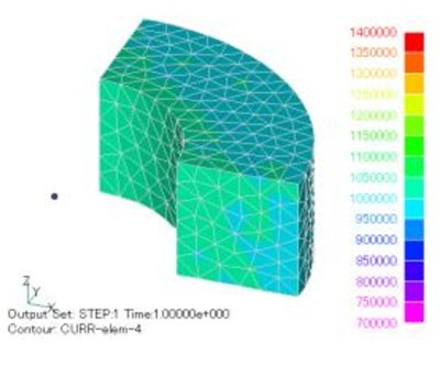
(a) SDEFCOIL
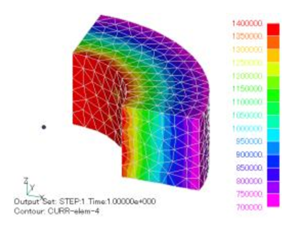
(b) PHICOIL
Fig.3 Current density intensity distribution
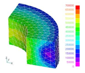
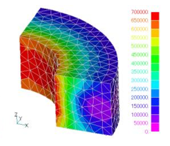
The magnetic flux density in the coil is shown in Fig. 4. It is slightly inward in the case of PHICOIL, but there is no noticeable difference. It can be said that there is almost no difference in the magnetic field outside the coil. Except for cases where the aspect ratio (coil radius coil cross-section width) is very small, the effect of the magnetic field due to current bias is considered to be small.
(a) SDEFCOIL
(b) PHICOIL
Fig.4 Magnetic flux density intensity distribution
The electromagnetic force density distribution obtained from the Lorentz force is shown in Fig. 5. Since the electromagnetic force is determined by the product of the current and the magnetic field, the current density bias will appear in the electromagnetic force. If it is important to obtain the electromagnetic force density distribution in a coil, it can be said that SDEFCOIL, which is closer to reality, should be used.
 (a)SDEFCOIL –>
(a) SDEFCOIL
(b) PHICOIL
Fig.5 Electromagnetic force density intensity distribution
In summary, in terms of use, SDFECOIL requires four sides to be defined, while PHICOIL requires only one side of the current inflow surface, making SDEFCOIL slightly more labor intensive, but not by much. In PHICOIL, if the coil has curvature, the current will be drawn to the inner diameter side. SDEFCOIL can be applied to coils with a square cross section, but if the coil is not rectangular, the current will be biased. If the coil is thin (coil cross-section length is smaller than coil circumference), these current biases are unlikely to be a problem. If the coil is thick and the internal electromagnetic force distribution is problematic, the effect of current bias is significant and the one that gives a more realistic current distribution should be used.
Download
・ input_PHICOIL
・ input_SDEFCOIL
・ pre_geom2D.neu :Mesh file
Analysis Examples by Functions
Current magnetic field source
- PHICOIL in rotational z-anti-mirroring symmetry
- Loop current defined by Potential Current Source (PHICOIL)
- PHICOIL at periodic boundaries
- SDEFCOIL and PHICOIL
- Steady-state DC+AC analysis of bulk conductors using PHICOIL and SUFCUR
- Heat generation output of current magnetic field sources
- DC current field analysis of bulk conductors
- Current Field Analysis on Periodic Boundaries
©2020 Science Solutions International Laboratory, Inc.
All Rights reserved.