Electromagnetic field analysis software

Electromagnetic field analysis software
Static magnetic field analysis using PHICOIL
- TOP >
- Analysis Examples by Functions (List) >
- Static magnetic field analysis using PHICOIL
Summary
So far, EMSolution has provided "ELMCUR (internal current source)", "SDEFCOIL (surface defined current source)" and "SUFCUR (surface inflow current source)" as functions to define the source current distribution within elements. ELMCUR basically specifies the amount of current that passes through the element plane of each element, and if the element arrangement is not regular, the amount of data to be set will be enormous. SDEFCOIL can only be used for coils with a square cross section, and the four planes surrounding the coil must be defined by surface elements, which is not easy to input. Also, SUFCUR cannot be used in static analysis and the current distribution is not fixed.
There is PHICOIL that makes up for the above drawbacks. PHICOIL is used to set electrical scalar potential in conductors and to define the current density from its gradient.
Explanation
Here we solve a steady-state current field in a conductor with a constant conductivity, given the electric scalar potential. For the coil definition, enter the physical property number of the coil conductor and the surface-element physical-property number of the current-inflow surface. Like SDEFCOIL and SUFCUR, surface definition is required, but it is easier to input than SDEFCOIL. It can be said that it is a DC version of SUFCUR, but it is assumed that the current distribution does not change. However, note that if the coil has a curvature in the current direction, the current density will be biased toward the inner radius of the coil. PHICOIL can be incorporated into the circuit in the same way as the conventional ELMCUR, SDEFCOIL and SUFCUR.
Figure 1 shows an application example. In this example, the x = 0 and y = 0 planes are mirror-symmetrical and Bn = 0. A current-inflow plane is defined on this symmetry plane. Current flows to the other symmetry plane. Figure 1 shows the current density distribution, but the current distribution is biased in the coil, and there is a difference of about 1.5 times. In case that it is easy to define SDEFCOIL with such a square cross section, SDEFCOIL is recommended. The orientation of the surface elements is free. Be sure to define the surface at the boundary of the analysis area. For reducing the current bias with PHICOIL, it is advisable to divide the coil cross section into parts and define each part with PHICOIL with different physical properties as shown in Fig.2. Here, the inflow-surfaces are also defined with different physical properties, but there is no problem even if they are defined with the same physical properties.
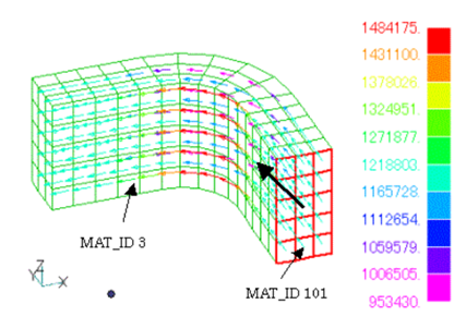
Fig.1 Application example of PHICOIL
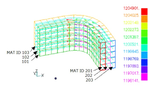
Fig.2 PHICOIL defined by dividing into multiple layers
Periodic boundary conditions can be defined in the same way. Define an inflow-plane at one end plane of the periodic boundary. The coil elements connected to the periodic boundary plane (the plane moved by one period) of this end plane must have the same physical property number. For example, consider the case where two helical coils are arranged facing each other as shown in Fig. 3 and the analysis is performed considering the periodicity of a half period. At this time, if the periodic symmetry condition (CYCLIC = 0) is used, currents in the same direction flow through the two coils as shown in Fig.4. Also, if periodic anti-symmetry (CYCLIC = 1) is used, the currents will be in the opposite direction as shown in Fig.5. It is important that the mesh on the coil end surfaces match on the symmetry planes. Also note that in this case, the definition of the current-inflow surface is just one.
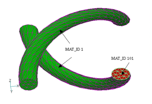
Fig.3 Two helical coils
When analyzing using periodic symmetry conditions

Fig.4 Current distribution under periodic symmetry conditions
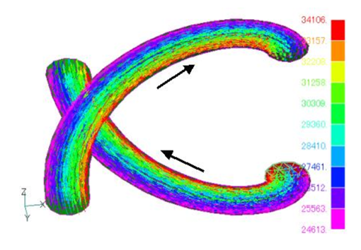
Fig.5 Current distribution under periodic antisymmetric conditions
How to use
This is an example of passing a current of 1500A through the current- inflow surface (ID 101).
Download
Fig.1
・ input
・ pre_geom2D.neu : Mesh file
・ 2D_to_3D : 2D mesh extension file
Analysis Examples by Functions
Static magnetic field
- Static magnetic field analysis using ELMCUR (element current source)
- Static magnetic field analysis using SDEFCOIL (surface defined current source)
- Regularization of SDEFCOIL (surface-defined current source)
- Static magnetic field analysis using PHICOIL
- Static magnetic field analysis using COIL (external current magnetic field source)
- Non-linear static magnetic field analysis
©2020 Science Solutions International Laboratory, Inc.
All Rights reserved.