Electromagnetic field analysis software

Electromagnetic field analysis software
Static magnetic field analysis using COIL (external current magnetic field source)
- TOP >
- Analysis Examples by Functions (List) >
- Static magnetic field analysis using COIL (external current magnetic field source)
Summary
The external current magnetic field source (COIL) can be placed independently of the mesh and does not require mesh division to match the coil shape.
Explanation
In this case, the region is divided into a total potential region including conductors and magnetic materials and a reduced potential region containing only air. Then place the coil in the reduced potential region. ELMCUR and SDEFCOIL must be within the total potential region. The electromagnetic force and current density of the coil itself are not output. In addition, since the inductance and resistance of these sources are not included in the finite element region, it is necessary to input them as external resistance and inductance when circuit calculation is required. When the external resistance and inductance are set to zero, only the voltage due to eddy currents, magnetization and interlinkage magnetic flux due to the magnetic field generated by ELMCUR and SDEFCOIL in the total potential region is output. COIL can move freely within the reduced potential region. The elements of COIL include straight lines (GCE), arcs (ARC), annulus (LOOP), and uniform magnetic fields (UNIF) with rectangular cross sections.
Now, we use the same analysis model as that used in "Static magnetic field analysis using ELMCUR (element current source)" and "Static magnetic field analysis using SDEFCOIL (surface defined current source)", and the meshing is done by using the automatic rectangular parallelepiped mesh generation function of EMSolution. Therefore, it is not necessary to input the mesh file, and specify the size and division of the rectangular parallelepiped in the input file. COIL data must be entered in all areas regardless of symmetry.
Figure 1 shows the calculated magnetic flux density distribution. The result is almost the same as that of ELMCUR and SDEFCOIL. The COIL mesh is generated for display. The convergence of the ICCG method does not go to $10^{-8}$ and diverges in the middle, but there is no problem. This is probably because the mesh is rough and the source term calculations contain errors.
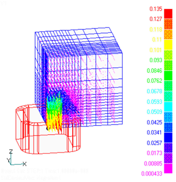
Fig.1 Model mesh and magnetic flux density distribution (T)
How to use
- Input mesh
Since the rectangular parallelepiped mesh generation function is used, no input mesh is required.
Specify the size and division of the rectangular parallelepiped mesh.
Specify the position, shape, etc. of COIL.
Download
・ input
・ pre_geom2D.neu : Mesh file
・ 2D_to_3D : 2D mesh extension file
Analysis Examples by Functions
Static magnetic field
- Static magnetic field analysis using ELMCUR (element current source)
- Static magnetic field analysis using SDEFCOIL (surface defined current source)
- Regularization of SDEFCOIL (surface-defined current source)
- Static magnetic field analysis using PHICOIL
- Static magnetic field analysis using COIL (external current magnetic field source)
- Non-linear static magnetic field analysis
©2020 Science Solutions International Laboratory, Inc.
All Rights reserved.