Electromagnetic field analysis software

Electromagnetic field analysis software
Analysis of Nonmagnetic Thin Plates with Surface Elements
- TOP >
- Analysis Examples by Functions (List) >
- Analysis of Nonmagnetic Thin Plates with Surface Elements
summary
This section introduces eddy current analysis of thin nonmagnetic conductors using plane elements. This function approximates thin nonmagnetic conductors with plane elements. Conventionally, even the thinnest conductor had to be divided into three-dimensional solid elements, but with this function, mesh division is simplified by simply embedding the plane elements in the mesh. Also, the need to create flat elements is eliminated, and the convergence of the analysis is expected to improve. This function can be used in combination with conventional solid elements.
explanation
Fig. 1 shows the results when a square thin plate conductor is approximated by a solid element in one half and by a plane element in the other half. The model is symmetrical in the y=0 and z= planes, and the square plate is 20 cm on each side and 1 cm thick. The conductivity is assumed to be 5 x 10⁷. The magnetic field is assumed to increase at 1 T/sec in the z direction, and the eddy current distribution at 0.1 sec is shown.
At this point, the eddy currents flow uniformly in the thickness direction and there is almost no skin effect. The equivalent thickness of 5 mm (top half) is input for the surface element. It can be seen that the current flows almost symmetrically. Also, List 1 shows the Joule heating at this time, which is almost the same on both sides. This shows that the same results can be obtained for both solid and surface elements. For this calculation, it is sufficient to approximate only the surface element.
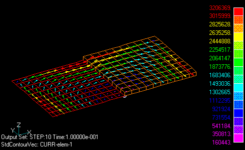
Fig.1 Eddy current distribution
(Half is approximated by a plane element)
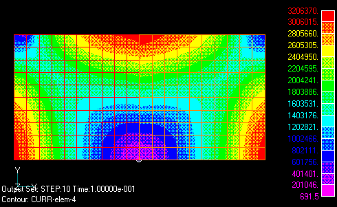
Fig.2 Eddy current density distribution
(Approximated with solid elements on the right half and plane elements on the left half)
List 1. contents of output file
********************************************************************************************************
*                            Step No.    10    Time   1.0000000000e-01 sec                             *
********************************************************************************************************

***  Sources   *********************************************************
       ID No.      Amplitude(Current)    Voltage              Flux
           1         1.00000e-01       -1.42397e+00       -5.58560e+01
***  Power Sources   ***************************************************
       ID No.         Current            Voltage
           1         1.00000e-01       -1.42397e+00

*** Total Joule heatin loss in regions  **********************
        MAT No.       Q (W)
           14       3.5195e+00    :Solid element part
            1       3.4611e+00    :Surface element part
        Total       6.9807e+00
Fig. 3 shows a solid element representation of a conductor with a large conductor thickness and a thin conductor with a plane element. You can see how the current spreads from the thin plate to the block. As you can see, solid and surface elements can be freely combined. However, the surface element cannot approximate a magnetic conductor. It is also not applicable when skin effects are expected and current density is expected to be distributed in the thickness direction.
Fig.3 Combination of surface and solid elements
Download
・ input
・ pre_geom.neu
Analysis Examples by Functions
Non-magnetic thin plate face elements
- Nodal and Lorentz forces in nonmagnetic materials
- Analysis of Rectangular Spiral Inductors
- Cutting of thin Conductor surfaces with gap elements (Part 2)
- Cutting of thin conductor surfaces with gap elements (Part 1)
- Analysis of Anisotropic Nonmagnetic Thin Plates
- Analysis of Nonmagnetic Thin Plates with Surface Elements
- Lorentz force acting on non-magnetic thin plate elements
©2020 Science Solutions International Laboratory, Inc.
All Rights reserved.