Electromagnetic field analysis software

Electromagnetic field analysis software
Cutting of thin conductor surfaces with gap elements (Part 1)
- TOP >
- Analysis Examples by Functions (List) >
- Cutting of thin conductor surfaces with gap elements (Part 1)
Summary
In "Intersection of Gap Elements", we discussed the case where a conductor solid element is cut by a gap element.
Explanation
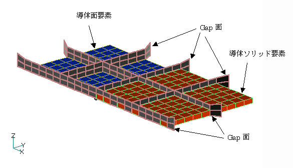
Fig.1 Analysis model
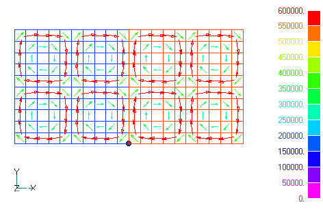
Fig.2 Distribution of eddy current density
Fig. 1 shows the analytical model.This model adds a gap plane to the model shown in "Analysis of a Nonmagnetic Thin Plate by Surface Elements". The conductor is approximated by solid elements for $x > 0$, and non-magnetic thin plate elements for $x < 0$. Symmetry is assumed for y = 0 and z = 0. Except for the gap surface, the conditions are the same as in "Analysis of a Nonmagnetic Thin Plate by Surface Elements". Fig.2 shows the resulting eddy current density distribution. There is good agreement on both sides of the solid and surface elements, and the gap surface has the same effect. Please note, however, that this mesh model has coarse partitioning and is not expected to be accurate. The input method for gap surfaces and conductor surfaces remains the same as before. In order to cut a thin conductor surface at the gap face, it is necessary to define a gap face at least one element layer from the conductor surface, just as with a solid element.
Download
・ input
・ pre_geom.neu
Analysis Examples by Functions
Non-magnetic thin plate face elements
- Nodal and Lorentz forces in nonmagnetic materials
- Analysis of Rectangular Spiral Inductors
- Cutting of thin Conductor surfaces with gap elements (Part 2)
- Cutting of thin conductor surfaces with gap elements (Part 1)
- Analysis of Anisotropic Nonmagnetic Thin Plates
- Analysis of Nonmagnetic Thin Plates with Surface Elements
- Lorentz force acting on non-magnetic thin plate elements
©2020 Science Solutions International Laboratory, Inc.
All Rights reserved.