Electromagnetic field analysis software

Electromagnetic field analysis software
Cutting of thin Conductor surfaces with gap elements (Part 2)
- TOP >
- Analysis Examples by Functions (List) >
- Cutting of thin Conductor surfaces with gap elements (Part 2)
Summary
Here is another example of cutting a non-magnetic thin plate surface with gap elements.
Explanation
Please refer to "Cutting of thin conductor surfaces with gap elements (Part 1)" first.
The model is shown in Fig. 1. The model is assumed to be symmetrical about the x=0 and y=0 planes, and a uniform external magnetic field is applied in the z direction. The lower part of the model is modeled with solid elements and is divided into 5 layers insulated by gap planes. The upper part is approximated by a 5-layer non-magnetic thin plate element. The thickness of the thin plate element is equal to the thickness of two layers of solid elements, so that the upper and lower parts have the same characteristics. Each surface is assumed to be divided into four sections by vertical gap planes. The analysis is assumed to be an AC steady-state analysis at 50 Hz; Fig.
2 shows the eddy current density distribution at phase 0 degrees. The third and eighth conductor plates from the bottom, at the same position on the top and bottom, are shown. The solid and thin plate face elements have approximately the same current flow. Fig. 4 shows the same object viewed from below. You can see that the distributions are almost the same at the top and bottom.
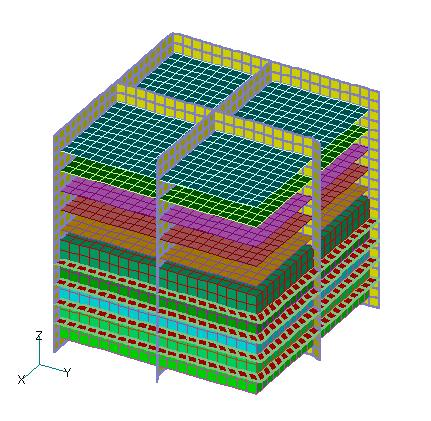
Fig.1 Analysis model
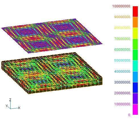
Fig.2 Eddy current density distribution of the third and eighth layers from the bottom
(phase 0 degrees)
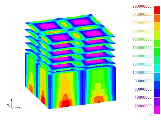
Fig.3 Time-averaged heat generation density distribution
(viewed from above)
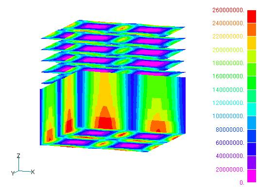
Fig.4 Time-averaged heat generation density distribution
(viewed from below)
List 1 shows the time-averaged total heating value for each conductor plate, with Mat No. 21 being the bottom plate. The upper thin plate conductor approximation is about 10% lower. This is likely due to the difference in modeling between the top and bottom. The skin effect seems to be better approximated by the solid element.
List 1 Time-averaged heat generation for each conductor plate
Download
・ input1
・ input2
・ pre_geom2D.neu
・ 2D_to_3D
Analysis Examples by Functions
Non-magnetic thin plate face elements
- Nodal and Lorentz forces in nonmagnetic materials
- Analysis of Rectangular Spiral Inductors
- Cutting of thin Conductor surfaces with gap elements (Part 2)
- Cutting of thin conductor surfaces with gap elements (Part 1)
- Analysis of Anisotropic Nonmagnetic Thin Plates
- Analysis of Nonmagnetic Thin Plates with Surface Elements
- Lorentz force acting on non-magnetic thin plate elements
©2020 Science Solutions International Laboratory, Inc.
All Rights reserved.