Electromagnetic field analysis software

Electromagnetic field analysis software
Analysis of Rectangular Spiral Inductors
- TOP >
- Analysis Examples by Functions (List) >
- Analysis of Rectangular Spiral Inductors
Summary
Taking the analysis of a rectangular spiral inductor as an example, we show the application of shell elements such as non-magnetic thin plate shell elements, surface impedance elements, and gap elements that can be used in EMSolution.
Explanation
Fig. 1 shows the model for this analysis.
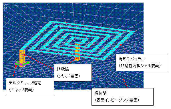
Fig.1 Analysis model
The rectangular spiral is assumed to have negligible thickness and is modeled with a non-magnetic thin plate shell element. That is, it is assumed that there is no skin effect and the current flows uniformly in the cross section. The shell properties are given as conductivity ($10^7S/m$) and thickness ($0.1 \mu m$). The spiral is assumed to be 10 mm square with a wire width of 0.5 mm, 0.5 mm between wires, and approximately 5 turns. The spiral is powered by a feed line represented by a solid element. The voltage from the power supply is provided in the middle of the feed line by a delta-gap feed. The delta-gap feed provides voltage above and below the gap. To give the feeding surface, a gap element is defined. The gap element protrudes one layer from the conductor as shown in the figure. The bottom surface is a sufficiently thick nonmagnetic conductor, defined by a surface impedance element, giving a conductivity ($10^7S/m$). The distance between the spiral and the bottom surface is 2 mm.
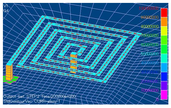
Fig.2 Three-dimensional mesh
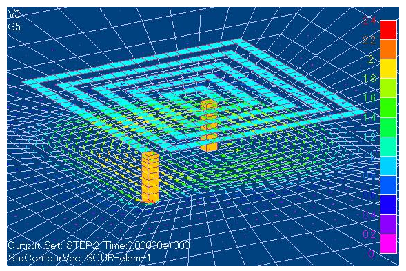
Fig.3 Eddy current distribution at the bottom
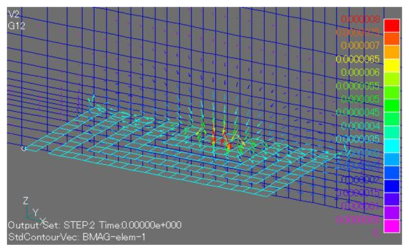
Fig.4 Magnetic flux density distribution
The current distribution in the spiral is shown in Fig. 2 when a voltage of 1 $V$ amplitude and 1 $MHz$ frequency is applied to the delta gap. Fig.3 shows the eddy current distribution on the bottom surface expressed by the surface impedance. In the surface impedance method, the current density in the thickness direction is integrated and expressed as an in-plane density ($A/m$). Fig. 4 shows the flux density distribution at the center of the spiral. The loop through the spiral surface can be seen.
From the calculated current amount, the overall impedance is calculated to be $205+0.59j(\Omega)$ in complex numbers. Equating this with $R+jωL$, resistance $R=205\Omega$ and inductance $L=9.5×10⁻⁸H$ are calculated. The total length of the spiral is about 103 mm, from which the resistance is calculated to be $207\Omega$, which is almost the same. The inductance depends on the distance to the bottom. In addition, the current may actually be distributed in the direction of the spiral line width, and a division in the line width direction may be necessary to achieve greater accuracy.
How to use
The element property definitions in the input file are as follows. Surface element property numbers 1, 4, and 5 represent non-magnetic thin plate elements, gap elements, and surface impedance elements, respectively.
In addition, delta-gap feeding is defined by surface inflow current sources (SUFCUR) as follows. The same property number 4 is used for the gap surface and the SUFCUR surface.
Download
・ input
・ pre_geom.neu
Note : Because of the large node number (27,600), this sample problem cannot be run in the trial version.
Analysis Examples by Functions
Non-magnetic thin plate face elements
- Nodal and Lorentz forces in nonmagnetic materials
- Analysis of Rectangular Spiral Inductors
- Cutting of thin Conductor surfaces with gap elements (Part 2)
- Cutting of thin conductor surfaces with gap elements (Part 1)
- Analysis of Anisotropic Nonmagnetic Thin Plates
- Analysis of Nonmagnetic Thin Plates with Surface Elements
- Lorentz force acting on non-magnetic thin plate elements
©2020 Science Solutions International Laboratory, Inc.
All Rights reserved.