Electromagnetic field analysis software

Electromagnetic field analysis software
Nodal and Lorentz forces in nonmagnetic materials
- TOP >
- Analysis Examples by Functions (List) >
- Nodal and Lorentz forces in nonmagnetic materials
Summary
In EMSolution, the electromagnetic force acting on a nonmagnetic conductor can be determined using the nodal force method and the Lorentz force method. Although the two methods are theoretically equivalent, they use different numerical analysis methods, and it is difficult to achieve perfect agreement due to discretization errors and other factors. In this section, I would like to explain the relationship and difference between the two. There are several ways to express electromagnetic force, such as electromagnetic force density, elemental force, nodal force, etc. EMSolution also outputs the distribution of electromagnetic force in several ways. Although these are just different ways of expressing the same thing, they look quite different when displayed as contour lines, etc., and many people may be confused. Here, I would like to explain them.
Explanation
First, the nodal force method directly integrates Maxwell’s stress tensor. Maxwell’s stress tensor in linear materials is
$$T_{ij} = H_i B_k – \delta_{ij} \frac{B \cdot H}{2} (1)$$and for nonmagnetic materials, the following relationship exists:
$$B = \mu_0 H (2)$$where $μ_0$ is the magnetic permeability of the vacuum. The electromagnetic force can be obtained by the spatial differentiation of Maxwell stress as follows:
$$f_i = \sum_{k=1}^3 \frac{\partial T_{ik}}{\partial x_k} (3)$$where $f_i$ is the directional component of the electromagnetic force density ($N/m^3$). In the nodal force method, the electromagnetic force density in Eq. (3) is multiplied by the nodal shape function and integrated in space to obtain the nodal force at node n, as shown below. Applying the integration by parts, the nodal force is expressed as follows:
$$F_{ni} = \int f_i \omega_n dV = \int \sum_{k=1}^3 \frac{\partial T_{ik}}{\partial x_k} \omega_n dV = – \sum_{k=1}^3 \int T_{ik} \frac{\partial \omega_n}{\partial x_k} dV (4)$$$ω_n$ is 1 at node n and 0 at other nodes and is a function that varies linearly within an element if it is a linear element. It has a value only within the element that shares nodal point n, and the integral in equation (3) is the integral only within the element that shares nodal point n. Note, however, that the integration function also has values in elements one layer outside of the conductor element that share a node on the conductor surface. As can be seen here, the nodal force method calculates the electromagnetic force from the magnetic fields B and H only. It is also a general method that is applicable for magnetic materials as well, although the form of Maxwell stress in equation (1) changes for nonlinear magnetic materials.
The element force in the nodal force method is obtained by assigning the obtained nodal force to the elements that share that node. That is, if the number of conductor elements sharing the nodal point is k, the nodal force is divided by k and added to each element. If conductors with different conductivity are in contact with each other, the distribution of the electromagnetic force should be different on both sides, but this is not taken into account. In the nodal force method, the nodal force is the basis, and the element forces are derived from it, so the nodal force is considered more accurate.
On the other hand, the electromagnetic force due to Lorentz force is expressed as
$$f = J \times B (5)$$and then integrates it in space to obtain. Equations (3) and (5) are equivalent for nonmagnetic materials, and equation (5) can be easily derived by substituting equations (1) and (2) into equation (3).
The nodal force of the Lorentz force is obtained by multiplying the Lorentz force by the nodal shape function and integrating it.
$$F_n = \int f \omega_n dV = \int ( J \times B ) \omega_n dV (6)$$Unlike the nodal force, the area of integration in Eq. (6) is only within the conductor element. In addition, the current density must be calculated separately. The term Lorentz force nodal force is confusing with nodal force in the nodal force method, but nodal force is a broader concept and is obtained differently by both methods. The elemental force in the Lorentz force method is obtained by volume integrating the electromagnetic force density in equation (5) at each element. In equation (6), set $ω_n$=1, and integrate within the element. The total element force and the total nodal force in the domain are the same. The element electromagnetic force density is obtained by dividing the element force by the volume. Below is an explanation of how the electromagnetic force is expressed by means of an analytical example.
As an analytical example, we will use the model used in “Lorentz force acting on a non-magnetic thin plate element”. Fig. 1 and 2 show the electromagnetic force density distribution obtained by the nodal force and Lorentz force methods. If FORCE_NORDAL=2 is specified in the post output, the electromagnetic force density is output as an element quantity calculated by dividing the element force obtained by both methods by the element volume. The agreement between the two methods is good. Since the electromagnetic force in a nonmagnetic material is generally distributed over a volume, this is the best way to display it.
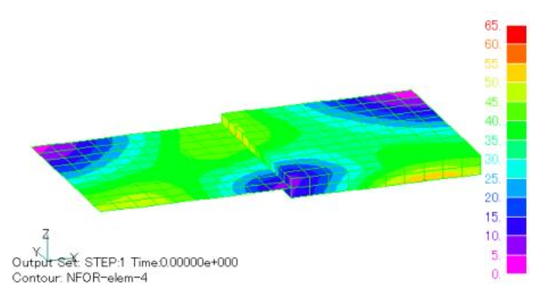
Fig.1 Electromagnetic force density intensity distribution($N/m^3$) by nodal force method
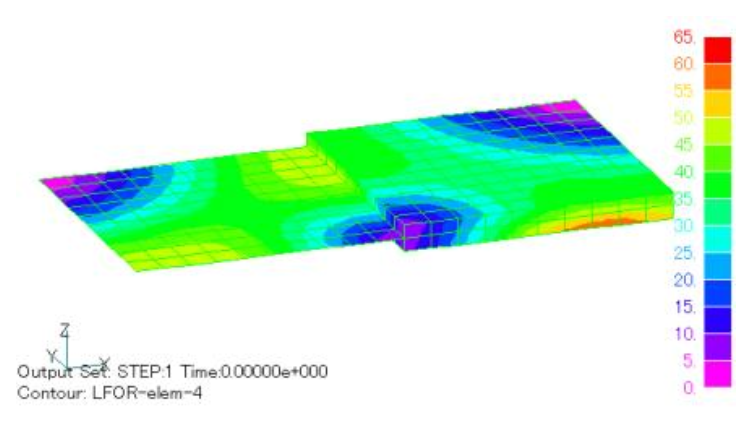
Fig.2 Electromagnetic force density intensity distribution ($N/m^3$)by Lorentz force method
If FORCE_NORDAL=1 and FORCE_J_B=1, the element force is output as an element quantity. The unit is N, which is the electromagnetic force acting on each element. The distribution of element forces is shown in Figs. 3 and 4. These are obtained by multiplying Figs. 1 and 2 by the volume of each element, respectively. For thin nonmagnetic elements, the area and thickness are multiplied instead. In this case, the element volume is multiplied, so if the element volume is different, the distribution of electromagnetic force density will be different from that in Figs. 1 and 2. In this example, the solid side has two layers, so the value is about half that of the surface element side.
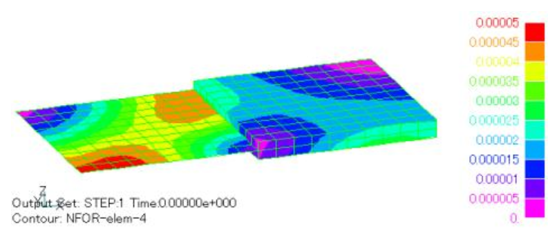
Fig.3 Electromagnetic element force distribution ($N$) by nodal force method
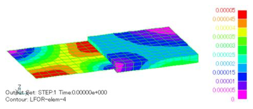
Fig.4 Electromagnetic element force distribution ($N$) by Lorentz force method
The distribution of nodal force is shown in Figs. 5 and 6, with the same output whether FORCE_NORDAL or FORCE_J_B is 1 or 2; the output is the nodal volume, in units of N. Although they represent the same thing as Figs. 5 and 6, they look quite different. The reason for this is due to the different method of obtaining the output as explained above. The nodal force is integrated by multiplying the force distributed at the elements sharing a node by the nodal shape function, so it depends on the number of elements sharing a node and the size of the element. Assuming the electromagnetic force density is constant, it is 1/8 of the element force at the corner nodes of a hexahedron, 1/4 at the ridges, and 1/2 at the surface (for a face element, 1/4 at the corners of a quadrangle and 1/2 on the edges). The same value is obtained at the nodes inside the conductor.
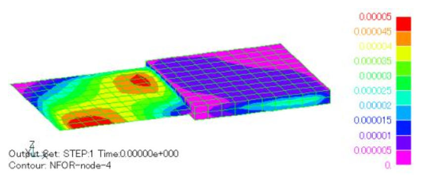
Fig.5 Electromagnetic nodal force distribution ($N$) by nodal force method
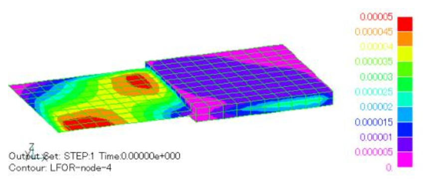
Fig.6 Electromagnetic nodal force distribution ($N$) by Lorentz force method
The distributional representation of nodal forces is not very intuitive in the case of volume-distributed forces such as those in nonmagnetic conductors. Nodal force is a concept that came out of stress analysis, and when a distributed force is given to stress analysis, it is commonly given as a nodal force (although volume forces are sometimes converted to nodal forces inside the stress analysis). Therefore, EMSolution’s nodal force output is a good form for handing over electromagnetic forces to stress analysis. Figs. 5 and 6, for nodes on the plane of symmetry (y=0 plane in this example), contributions from elements on the opposite side of the plane of symmetry are added, and the distribution appears smooth in the plane of symmetry. Since this is not necessary when performing stress analysis, the output functions shown in Figs. 7 and 8 are provided for stress analysis; setting FORCE_NORDAL=-1 or -2 and FORCE_J_B=-1 or -2 will result in this output. The output of the element amount is the same as when FORCE_NORDAL、FORCE_J_B are set to 1 or 2, respectively. In this case, the contributions on the opposite side of the plane of symmetry are not added, resulting in a discontinuous distribution in the plane of symmetry. In this case, the nodal points on the y=0 plane have half the values of Figs. 5 and 6.
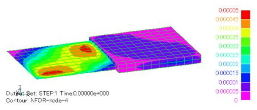
Fig.7 Nodal force distribution for electromagnetic force stress analysis ($N$) by nodal force method
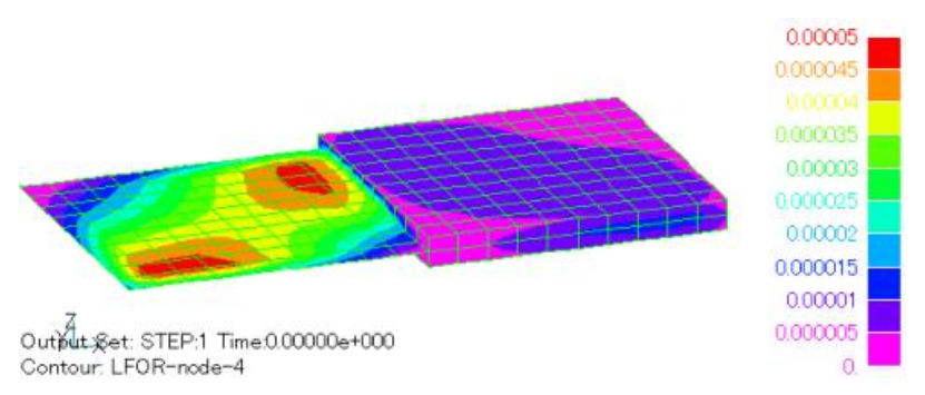
Fig.8 Nodal force distribution for electromagnetic force stress analysis ($N$) by Lorentz force method
In the example shown here, the nodal force method and the Lorentz force method agree well, but please note that there are cases where the agreement is not good, as described in “Lorentz force acting on a non-magnetic thin plate element”. In the case of magnetic materials, the Lorentz force method is not applicable, and only the nodal force method can be used. In this case, the concept is the same, but please note that the electromagnetic force mainly appears on the surface of the magnetic material and may vary greatly depending on the display method.
Analysis Examples by Functions
Non-magnetic thin plate face elements
- Nodal and Lorentz forces in nonmagnetic materials
- Analysis of Rectangular Spiral Inductors
- Cutting of thin Conductor surfaces with gap elements (Part 2)
- Cutting of thin conductor surfaces with gap elements (Part 1)
- Analysis of Anisotropic Nonmagnetic Thin Plates
- Analysis of Nonmagnetic Thin Plates with Surface Elements
- Lorentz force acting on non-magnetic thin plate elements
©2020 Science Solutions International Laboratory, Inc.
All Rights reserved.