Electromagnetic field analysis software

Electromagnetic field analysis software
Post data output in arbitrary coordinate system
- TOP >
- Analysis Examples by Functions (List) >
- Post data output in arbitrary coordinate system
Summary
Until now, EMSolution has output all results from electromagnetic field analysis in the overall coordinate system, which is a Cartesian coordinate system. However, depending on the target device, for example, in a rotating machine, it may be more convenient to output vector quantities such as magnetic flux density in a cylindrical coordinate system. We are pleased to report that it is now possible to output post data in an arbitrary coordinate system.
Explanation
This function is explained using the IEEJ benchmark model “D model” shown in Fig. 1. D model is a 4-pole, 24-slot IPM motor. For details, please refer to Reference [1]. The analysis is a two-dimensional current source analysis, with a rated current of 3 $Arms$, a current advance angle of $\beta$ of 25 deg, and a torque of 1.8 $Nm$ at a speed of 1500 $min^{-1}$. The magnetic flux density distribution is shown in Fig. 2 and the electromagnetic force density distribution in Fig. 3, which were analyzed as before and output in the cylindrical coordinate system using this function when outputting post data. The electromagnetic force is concentrated at the tip of the teeth, and the radial component Fr, which is the cause of the electromagnetic excitation force, and the circumferential component $F_\theta$, which is the cause of torque, can be seen separately. Here, the electromagnetic force is calculated by the nodal force method, and the data shown are element-averaged quantities ($N/m^3$).
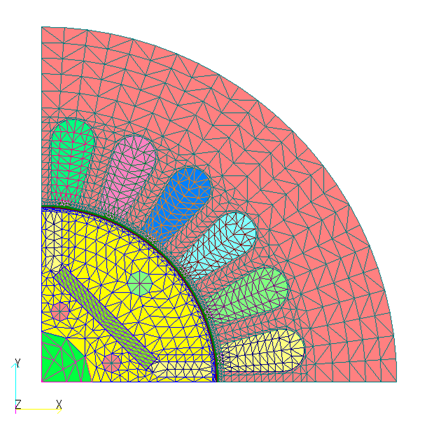
Fig.1 IEEJ Benchmark Model: D model
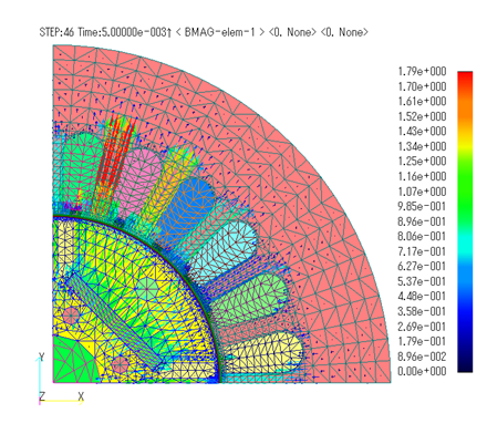
(a) Radial direction magnetic flux density component $B_r$
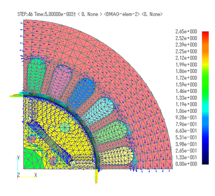
(b) Circumferential magnetic flux density component $B_\theta$
Fig.2 Magnetic flux density distribution (T)
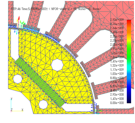
(a) Radial Electromagnetic Force Density Component $F_r$
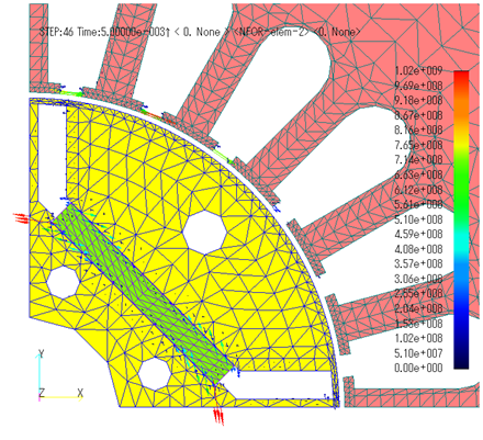
(b) Circumferential electromagnetic force density component $F_\theta$
Fig.3 Electromagnetic force density distribution ($N/m^3$)
When this function is used, the vector quantity output to the output file is also output in an arbitrary coordinate system. Fig. 4 shows the radial component $F_r$ and circumferential component $F_\theta$ of the electromagnetic force output to the output file. Since the stator and rotor electromagnetic forces coincide due to action-reaction, the sign of the stator electromagnetic force is reversed. This shows that the electromagnetic force of the radial component is considerably larger than that of the circumferential component. We have confirmed that the electromagnetic force of the circumferential component multiplied by the rotor diameter (or more precisely, the distance to the gap center) is equal to the torque.
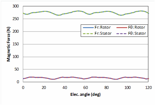
Fig.4 Electromagnetic force waveform
– Additional function – Moment output function in local coordinate system –
In this functionality released in 2012/10 with r10.4.1, the axis of the moment output to the output file was assumed to pass through the origin. We have now made it possible to output moments in the local coordinate system. Physical quantities other than moments can be output in a user-defined coordinate system in r10.4.1 as well. As a simple example, Fig. 5 shows the verification model: a magnetic cylinder with a radius of 0.1$m$ and a specific permeability of 1000, centered at 1$m$ in the X direction, and a rotating uniform magnetic field (UNIF) in the XY plane at 50$Hz$. As a relative motion, it is the same if we consider that the cylinder rotates under uniform magnetization. The periodic boundary condition is set at 20 degrees in the circumferential direction.
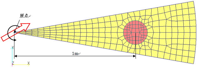
Fig.5 Verification model for moment output in local coordinate system
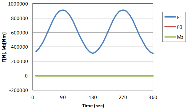
The radial electromagnetic force $F_r$ and circumferential electromagnetic force $F_\theta$ acting on the magnetic cylinder in the cylindrical coordinate system at the origin and the electromagnetic force moment around the Z axis are shown in Fig. 6. The radial electromagnetic force is large and always positive. The center of the cylinder is X=1m, but the magnetic cylinder has a size (not a mass point), so there is a difference in $F_\theta$ and Mz, but both are positive and negative oscillating forces.
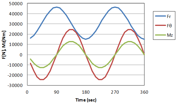
Fig.6 Electromagnetic forces and moments at origin in cylindrical coordinate system
Next, the electromagnetic forces and moments in a cylindrical coordinate system centered at the magnetic center (X=1$m$) are shown in Fig. 7. In this case, Fr becomes dominant, and the force $F_\theta$ that tries to rotate around the magnetic body center is quite small. Since the radius of the cylinder is 0.1$m$, Mz is almost 1/10 of $F_\theta$. This analysis shows that the moment around the center of the cylinder is also working, although it is smaller than the moment around the origin.
(a)$F_r$, $F_θ$, Mz
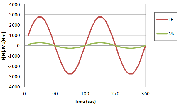
(b)$F_θ$, Mz
Fig.7 Electromagnetic forces and moments in cylindrical coordinate system
In addition to magnetic flux density and electromagnetic force, eddy current density and Lorentz force can also be output in a cylindrical coordinate system. the electromagnetic and Lorentz forces in the output file are also output in the specified coordinate system.
References
(1) “Practical Performance Evaluation Technology for Rotating Machines by Electromagnetic Field Analysis”, IEEJ Technical Report No. 1244 (2012)
How to use
By setting the local coordinate COORD_ID defined in “Handbook 12.2. Local Coordinate System” to the option POST_COORDINATE in “Handbook 10.2 Output Files (continued)”, the chain flux calculation loop will output post data in that local coordinate system. This function can also be performed only with post processing POST_PROCESSING=1.
The X component is output as the $R$ component and the Y component as the $\theta$ component in the post data, such as BMAG-elem-1: $B_r$ and BMAG-elem-2: $B_\theta$, in the magnetic and force files. However, B_INTEG and COIL_force are not supported.
Download
IPM Motor Model
- input2D_3A25deg.ems : Magnetostatic field solution
- pre_geom2D.neu : Stator
- rotor_mesh2D.neu : Rotor
Additional function: Moment output in arbitrary coordinate system
- input2D.ems
- input2D_post1.ems : Moment post processing output around origin
- input2D_post2.ems : Moment post-processing output around magnetic body center
- pre_geom2D.neu : Stator
Analysis Examples by Functions
Pre-post function
- Post data output in arbitrary coordinate system
- Improvement of surface element output and 180-degree rotational periodic symmetry conditions for boundary surfaces
- Output of boundaries between total and reduce potential regions when using COIL
- ICCGの反復回数をMax Iteration回で打ち切る
- Specifying output elements
- Addition of heat generation density distribution output to the elm file format
- Surface element output of electromagnetic force by nodal force method
- Frequency decomposition in post-processing
©2020 Science Solutions International Laboratory, Inc.
All Rights reserved.