Electromagnetic field analysis software

Electromagnetic field analysis software
Output of boundaries between total and reduce potential regions when using COIL
- TOP >
- Analysis Examples by Functions (List) >
- Output of boundaries between total and reduce potential regions when using COIL
Summary
When using COIL as an external coil, the COIL definition region must be specified as the reduced potential region and the conductor or magnetic material as the total potential region. Furthermore, when calculating the electromagnetic force of a magnetic body as shown in Fig. 1, it is necessary to define the total potential region from the magnetic body to the air region one layer outside the magnetic body. In this case, the total potential region can be further extended by using the EXTEND_TOTAL option. However, if the magnetic material and COIL are close to each other, it is necessary to check whether the total potential region over COIL exists by using the EXTEND_TOTAL option. We have now created a function that outputs the boundaries of the total potential region and reduced potential region in the t_r_interface file by default when COIL is used. In addition, we have added an option COIL_OPTION to output COIL mesh to the post_geom mesh data file for post-processing. In addition, the output file option NO_OUTPUT_MATS can now be applied to post_geom as well, although only the properties specified in NO_OUTPUT_MATS can be output to the post data file.
Explanation
The plunger model of TEAM Workshop Problem 20, shown in Fig. 1, which is employed in the EMSolution benchmark test, is used for the introduction. A coil is wound around a magnetic pole, and the coil is defined by COIL. Since this benchmark model is for electromagnetic force verification, the electromagnetic force is output as nodal force (NODAL_FORCE), but the EXTEND_TOTAL option is used since all air region other than magnetic material is assumed to be in the reduced potential region. Fig. 2 shows the boundary surfaces and COILs of the total potential and reduced potential regions output in the t_r_interface file. It can be seen that the boundary surfaces of the total potential region and the reduced potential region are output as surface elements in the area excluding the boundary condition surface, and do not intersect with the COIL. Note that the COIL mesh is always output in the t_r_interface file, regardless of whether COIL_OPTION is On Off.
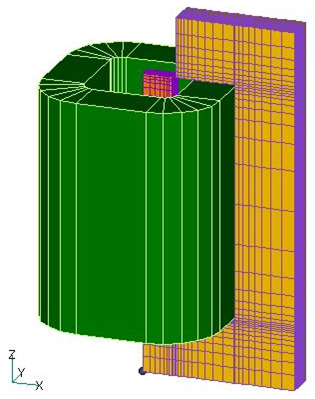
Fig.1 Problem20
Analysis model
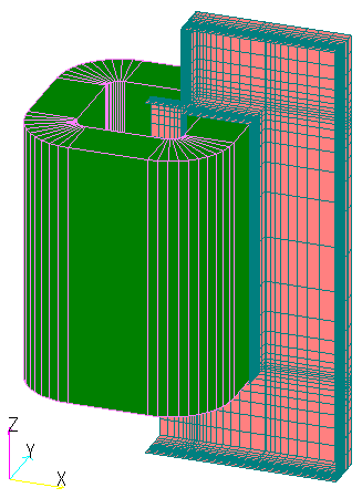
Fig. 2 Boundary surface of total potential region and reduced potential region of Problem 20
These should make it easier to check the boundary surfaces of the total potential region and the reduced potential region. In particular, when using DEFORM or COIL_MOTION, it should be noted that the boundary surface between the total and the deformation potential region is expected to change. It is recommended to check visually with this function.
How to use
The boundary surfaces between the total potential region and the reduced potential region are output as surface elements and COIL mesh in the t_r_interface file by default when COIL is used. Whether or not COIL is output to the post_geom file can be specified by setting the COIL_OPTION option to 0: Yes (default) or 1: No.
Analysis Examples by Functions
Pre-post function
- Post data output in arbitrary coordinate system
- Improvement of surface element output and 180-degree rotational periodic symmetry conditions for boundary surfaces
- Output of boundaries between total and reduce potential regions when using COIL
- ICCGの反復回数をMax Iteration回で打ち切る
- Specifying output elements
- Addition of heat generation density distribution output to the elm file format
- Surface element output of electromagnetic force by nodal force method
- Frequency decomposition in post-processing
©2020 Science Solutions International Laboratory, Inc.
All Rights reserved.