Electromagnetic field analysis software

Electromagnetic field analysis software
Improvement of surface element output and 180-degree rotational periodic symmetry conditions for boundary surfaces
- TOP >
- Analysis Examples by Functions (List) >
- Improvement of surface element output and 180-degree rotational periodic symmetry conditions for boundary surfaces
Summary
EMSolution uses an internal method to automatically recognize periodically symmetric surfaces and far boundaries (Far boundary) when setting boundary conditions, except for inputs using surface specifications such as $B_n$=0 and $H_t$=0. However, as described in "Effect of Geometry Data Accuracy in Sliding Method", if there is a mesh error, the periodic boundary surface will not be recognized as a periodic boundary surface and the results may not be correct. To allow for a certain amount of mesh error, the DISTANCE_JUDGE parameter is used as a discriminant value to determine whether nodes are on the specified surface or the periodic boundary surface. However, the output information on whether the periodic boundary surface is set as intended by these settings is scarce, and the actual confirmation method has been to judge by looking at the calculation results. Now, we have added a function that outputs the recognized boundary surface as a surface element as a reliable means of confirmation. In addition, the number of nodes and edges on the periodic boundary surface are output to an output file.
Explanation
Surface element output function for boundary surfaces
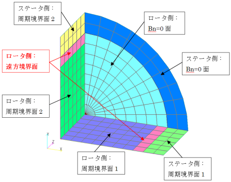
The model used in "Effect of Geometry Data Accuracy on Slide Method" shown in Fig. 1 is used for the explanation. In this model, the nodes on the sliding surface are intentionally shifted 0.1 degree around the Z axis, which is the axis of rotation, and DISTANCE_JUDGE=0.0001 is set so that the rotation period symmetry condition is not applied. The surface element output using the surface element output function for boundary surfaces is shown in Fig. 2. It can be seen that the surface containing the intentionally displaced nodes is recognized as a far boundary surface instead of a periodic boundary surface.
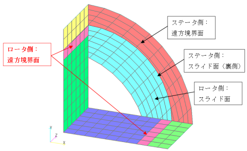
The number of nodes on the periodic boundary face "on periodic face" output in the output file is also reduced from the original 112 to 98. Fig. 3 shows the boundary surface element with DISTANCE_JUDGE = 0.01, which confirms that the periodic boundary face is correctly recognized by setting DISTANCE_JUDGE larger than the 0.1 degree deviation.
Note that a sliding plane is identified as a sliding plane when the sliding edge is rotated in the direction of motion and the nodes are on the same plane, so in this case of 0.1 degree deviation of rotational motion, it is on the same plane and thus is recognized as a slide plane.
The reason why the far boundary is recognized as a far boundary surface is that EMSolution removes the surfaces for which boundary conditions are specified from the outer surfaces of the extracted whole mesh and sets far boundary conditions on the remaining boundary surfaces. Therefore, if there is an error at a node on a symmetric boundary surface such as $B_n$=0, regardless of the periodic boundary surface, it may be set as a far boundary condition. The best way to prevent such a problem is to increase the mesh accuracy, but as shown in Fig. 3, it may be possible to use a slightly larger value for DISTANCE_JUDGE. However, if, for example, a model with a fine mesh to account for skin effects has a small minimum nodal distance and the boundary surface has an error greater than the minimum nodal distance, the mesh accuracy must be increased to deal with the problem. Note that if DISTANCE_JUDGE is set larger than the minimum nodal distance, the two nodes that are originally separate will be recognized as the same node, resulting in problems such as collapsed elements.
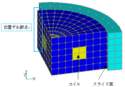
Fig.1 Mesh System Verification Model
(a) Entire boundary surface
(b) Excluding $B_n$=0 surface
Fig.2 Display of boundary surface elements (with mesh error)
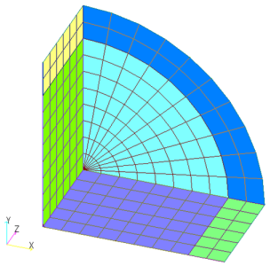
Fig.3 Display of Boundary Surface Elements (without mesh error)
This function is also useful as a check for inconsistently created meshes. As a simple example, we will examine the mesh shown in Fig. 4. This mesh intentionally has a different number of mesh divisions and double nodes. Since the surfaces do not join at these locations, they are recognized as boundary surfaces and the far boundary condition is applied. In such cases, it is thought that the mesh problem can be resolved by checking the output function of the boundary surface shown in Fig. 5. We hope you will use this function as a confirmation before running this calculation.
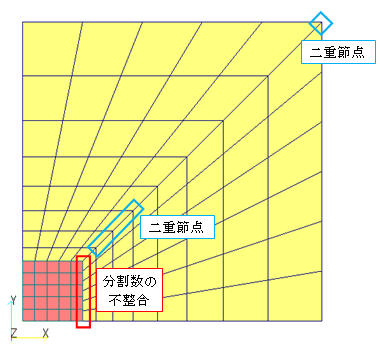
Fig.4 Inconsistent mesh for verification (2D)
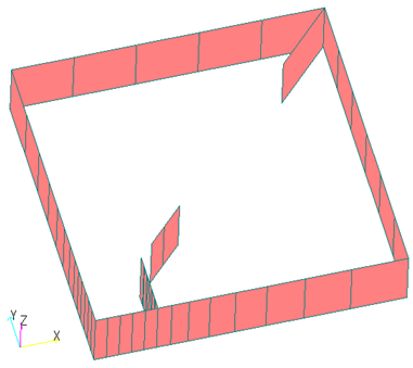
Fig.5 Confirmation by outputting boundary surface elements
(far boundary surfaces only)
* Surfaces in meshes are inconsistent.
Improved 180-degree rotational periodic symmetry condition
As described in "Bug in 180 Degree Rotation Periodic Analysis", EMSolution version r10.2.2 and later have supported the 180 degree rotation periodic symmetry condition as a stopgap measure with the following limitation:
The mesh is created with Y > 0, one of the periodic boundaries is X > 0 and the other is X < 0, and the periodic boundary does not exceed +90 degrees due to skew or other reasons.
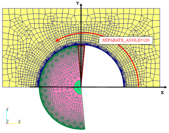
In the case of a model with 180-degree rotation periodic boundary, such as the induction motor shown in Fig. 6, even if the mesh was skewed, it could be calculated without any problem as long as the mesh was defined as shown in Fig. 6(b) to satisfy the above conditions. However, if one of the periodic boundary planes spanned both X <0 and X>0, as shown in Fig. 4(c), the above limitation was partially exceeded, and the periodic boundary plane was not recognized correctly. Starting with EMSolution version r11.1.1, a new option, SEPARATE_ANGLE, has been added as a required item to explicitly specify the separation of periodic boundary surfaces when setting the 180-degree rotational periodic symmetry condition.
The reason for this is that EMSolution has been able to automatically recognizes complex periodically symmetric surfaces by automatically identifying nodes that are candidates for periodic boundary surfaces if they match when moved by a periodic symmetry length or rotated by a periodic symmetry angle.
This allows for correct recognition in the case of translational periodic symmetry and rotational periodic symmetry of less than 180 degrees. However, in the case of 180-degree rotational periodic symmetry, there is an inconsistency in that there is a matching partner no matter which of the two candidate surfaces is rotated. For this reason, we have decided to use SEPARATE_ANGLE to separate the two surfaces to eliminate the aforementioned limitation.
As an example, in Fig. 6(b), the skew is about 5.295 degrees per lotus slot, so the angle at which the periodic boundary plane can be separated from the mesh definition position is 5.295 degrees < SEPARATE_ANGLE < 174.705 degrees, and any degree in between is acceptable. In this example, SEPARATE_ANGLE is set to be 90 degrees for simplicity. In In Fig. 6(c), the rotor side is defined as 95.295 degrees < SEPARATE_ANGLE < 264.705 degrees, and the stator side as 0 degrees < SEPARATE_ANGLE < 180 degrees, so SEPARATE_ANGLE = 120 degrees which allows both boundary surfaces to be separated. This specification ensures that the 180-degree rotational periodic symmetry condition is correctly recognized and computed correctly. (From r10.2.2 to r11.0.1, this was equivalent to specifying SEPARATE_ANGLE = 90 degrees.)
Note that SEPARATE_ANGLE specifies an angle from the X axis, regardless of the mesh definition position, and applies to both stator (pre_geom) and rotor (rotor_mesh). Therefore, SEPARATE_ANGLE is applied to the mesh definition position (nodal coordinates), so please make sure that the mesh definition positions of the stator and rotor are within the SEPARATE_ANGLE specification (the initial position of the rotor can be changed with the time function). In addition, for models where the entire mesh exceeds 360 degrees due to skew, etc. (models that are skewed 180 degrees or more), the 180-degree rotation periodic symmetry condition cannot be set even with this function, so use a 360-degree model for the analysis. To check if SEPARATE_ANGLE is specified correctly, use the previous boundary surface element output function to check the periodic boundary surfaces.
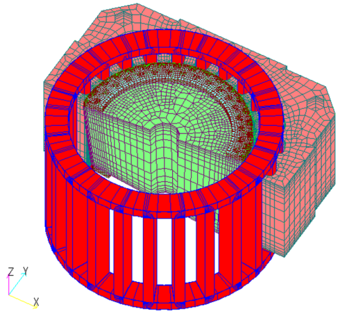
(a) Bird’s eye view (excluding air)
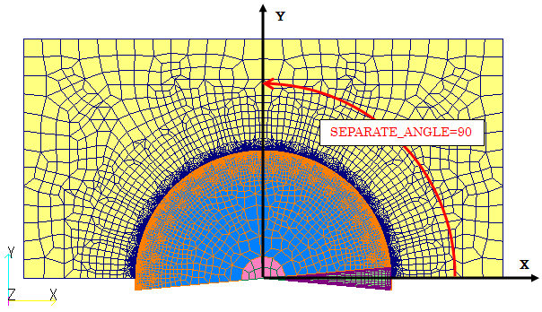
(b) XY plan view (excluding coils) of Y>0 skew model
(c) XY plan view (excluding coil) of rotor X<0 skew model
Fig.6 Example of 180-degree rotation periodic symmetry model
Three-dimensional induction motor model
How to use
Using the Surface Element Output Function for Boundary Surfaces
There is no option for the surface element output function of the boundary surface. If POST_DATA_FILE > 0 in "Handbook 10. Input/output files", the output is output as a boundary_surface file with the specified mesh format during PRE_PROCESSING. The physical property number (MAT_ID) assigned to the surface element is automatically assigned according to the input mesh file and boundary conditions as follows.
Note that even if a second-order node element is tangent to the boundary surface, it is output as a first-order surface element. The number of nodes and edges on the periodic boundary surface are output as "on periodic face" in the output file.
| pre_geom | rotor_mesh | rotor_mesh n (n=2~7) |
||
|---|---|---|---|---|
| Ht=0面 | MAT_ID=1 | MAT_ID=101 | MAT_ID=n01 | (例:201) |
| Bn=0面 | MAT_ID=2 | MAT_ID=102 | MAT_ID=n02 | (例:202) |
| 遠方境界面 (Type=0,1,3) | MAT_ID=3 | MAT_ID=103 | MAT_ID=n03 | (例:203) |
| 表面 インピーダンス | MAT_ID=4 | MAT_ID=104 | MAT_ID=n04 | (例:204) |
| 無限境界要素面 (Type=2) | MAT_ID=5 | MAT_ID=105 | MAT_ID=n05 | (例:205) |
| スライド面 | MAT_ID=11 | MAT_ID=111 | MAT_ID=n11 | (例:211) |
| 周期境界面 | MAT_ID=21,22 | MAT_ID=121,122 | MAT_ID=n21,n22 | (例:221,222) |
How to use the correction function for 180-degree rotational periodic symmetry conditions
In EMSolution version r11.1.1 or later, to use the 180-degree rotational periodic symmetry condition, SEPARATE_ANGLE must be entered in the column following ANGLE. SEPARATE_ANGLE sets the angle around the Z axis from the X axis, independent of the mesh definition position (nodal coordinates). SEPARATE_ANGLE should be set to an angle that does not cross the periodic boundary plane.
Note that this option is only required for 180-degree rotational periodic symmetry. Please refer to the Handbook "14. Periodic Boundary Condition, Sliding Surface" for a summary of how to use this option.
Download
Mesh accuracy verification model
- input.ems
- pre_geom2D.neu
- rotor_mesh2D.neu
- 2D_to_3D
Analysis Examples by Functions
Pre-post function
- Post data output in arbitrary coordinate system
- Improvement of surface element output and 180-degree rotational periodic symmetry conditions for boundary surfaces
- Output of boundaries between total and reduce potential regions when using COIL
- ICCGの反復回数をMax Iteration回で打ち切る
- Specifying output elements
- Addition of heat generation density distribution output to the elm file format
- Surface element output of electromagnetic force by nodal force method
- Frequency decomposition in post-processing
©2020 Science Solutions International Laboratory, Inc.
All Rights reserved.