Electromagnetic field analysis software

Electromagnetic field analysis software
Two-Dimensional Cogging Torque Analysis for Permanent Magnet Motors
- TOP >
- Analysis Examples by Functions (List) >
- Two-Dimensional Cogging Torque Analysis for Permanent Magnet Motors
Summary
Here we analyze the cogging torque of a permanent magnet motor in two dimensions. In EMSolution, such an analysis is performed by considering a sliding surface in the gap space between the stator and the rotor, with both parts moving along the sliding surface.
Explanation
First, create a 2D mesh of the rotor and stator with triangles and squares as shown in Fig.1 and Fig.2. Here, the meshes are made in CRC/ATLAS, and the file names are rotor_mesh2D and pre_geom2D, respectively. If you made them in FEMAP, please put .neu extension. The outermost surface of the rotor and the innermost surface of the stator shall be on the same circle (on the sliding surface). Also, each must have at least one layer of air in contact with the sliding surface. The meshes in the direction of motion in contact with the sliding surface do not necessarily have to be equally spaced, and the meshes of the rotor and stator do not have to be the same, but as little difference as possible will make the calculation more stable. In the two-dimensional mesh, to define the sliding surface, a point on the sliding surface is added in the rotor mesh as a point element (Mass elements in the case of FEMAP).
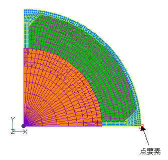
Fig. 1 Rotor analysis mesh
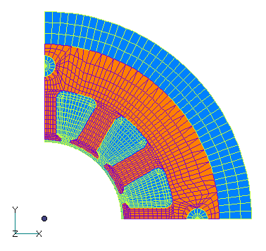
Fig.2 Stator analysis mesh
In the file input, enter the boundary conditions (90-degree antisymmetric periodic boundary conditions), division of the sliding surface in the direction of motion, magnetization of the magnet, rotation speed, and magnetic material properties. The division of the sliding surface should be approximately the same as the division of the mesh. If the division width of the sliding surface in the direction of motion is less than about 1/2 of the mesh division width, the calculation will be unstable. Calculations are performed continuously, with rotation given according to the input. In this case, the rotation speed is irrelevant because this is a magnetostatic analysis that does not include eddy currents. Fig. 3 shows the magnetic flux density distribution arrow diagram when the rotor rotates 15 degrees. These are mainly forces of attraction between the stator and rotor. The torque in the rotational direction is derived by integrating these forces in the rotational direction. The calculated results of the angle dependence of the cogging torque are shown in Fig. 5. Fig. 6 shows the measured values and the results from other programs (three-dimensional analysis). The results here are slightly larger because of the two-dimensional analysis, but they are in good agreement. Fig. 5 plots both the rotor side and stator side integrated torque, and they are in good agreement. They should be in agreement with each other in action-reaction.
Fig.3 Magnetic flux density arrow diagram (15 degrees)
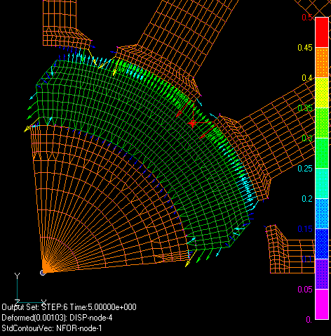
Fig.4 Nodal force distribution
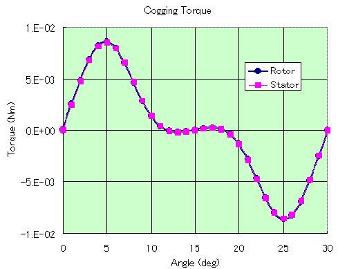
Fig.5 Angle dependence of torque
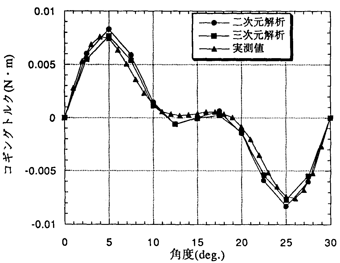
Fig.6 Measured values and other analysis results
Literature
IEEJ Technical Report No. 565, “High-Precision Numerical Simulation Techniques for Electromagnetic Fields in Rotating Machines”, October 1995, 24 pages.
Download
Analysis Model
・ input.ems : Input condition file
・ pre_geom2D.neu : Stator mesh file
・ rotor_mesh2D : Rotor mesh file
Analysis Examples by Functions
Analysis of permanent magnet motors
- Application of COIL to Motor Windings
- Impact Load Analysis of Brushless DC Servo Motor
- Dynamic Analysis of DC Brushless Servo Motor (ON-OFF function based on SWICH position)
- Analysis of DC brushless servo motors (using switch function)
- Three-Dimensional Cogging Torque Analysis for Permanent Magnet Motors
- Two-Dimensional Cogging Torque Analysis for Permanent Magnet Motors
©2020 Science Solutions International Laboratory, Inc.
All Rights reserved.