Electromagnetic field analysis software

Electromagnetic field analysis software
Dynamic Analysis of DC Brushless Servo Motor (ON-OFF function based on SWICH position)
- TOP >
- Analysis Examples by Functions (List) >
- Dynamic Analysis of DC Brushless Servo Motor (ON-OFF function based on SWICH position)
Summary
In "Analysis of DC brushless servo motors (using switch function)" an example analysis of a brushless DC servo motor was presented. In that analysis, we solved a coupled problem with a circuit containing a switch, assuming that the rotational motion of the rotor is given as constant. In this section, we discuss an example of a coupled motion problem in which the rotational motion itself is also taken into account. In addition, since EMSolution ver10.1, we have added a function to turn ON/OFF the SWITCH of the Network module in relation to its position.
Explanation
To perform this analysis, the Dynamic and Network modules of EMSolution are required.
The analysis model is shown in Fig. 1. This model is the one used in "Analysis of a Brushless DC Servo Motor (using switch function)", and is a two-dimensional nonlinear analysis. The boundary condition is set to a 4-fold counter-rotating periodic boundary condition.
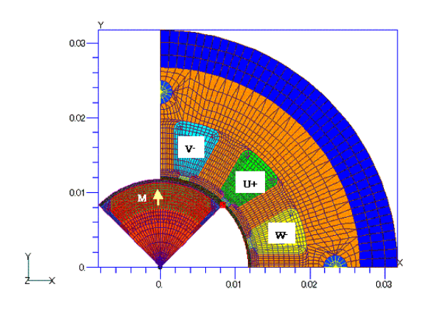
Fig. 1 Analysis model and mesh
First, we consider the position where the rotor is at rest with zero winding current. If no external torque is applied to the rotor, the rotor is considered to be at rest at the position where the electromagnetic force torque (cogging torque) is zero. The angle dependence of the cogging torque is shown in Fig. 2. In this document, the position in Fig. 1 is assumed to be zero and clockwise is positive; note that the position and torque are shown inverted because EMSolution’s angular forward direction is counterclockwise. From Fig. 2, we can see that the stable equilibrium point (the angle at which the torque crosses zero from positive to negative) is in the neighborhood of ±3 degrees, which is a stable static position. This position is determined by the motion of the rotor.
The initial angle of the rotor is 1 degree, and a coupled analysis of the motion is performed. Fig. 3 shows the resulting angular variation with no frictional force on the rotor (C1=0) and with a frictional force proportional to the rotation speed ($C1=1.E-5 (Nm/(deg/s)$). In the absence of friction, the rotor is oscillating around a stable equilibrium point. No friction means no loss, so no damping is observed. With friction, convergence to the equilibrium point and rest can be seen. The stationary angle of 3.26 degrees corresponds to the stable equilibrium point shown in Fig. 2.
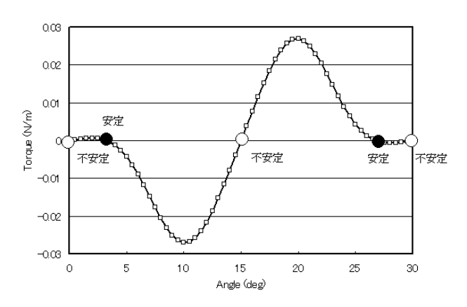
Fig.2 Cogging torque angle dependence
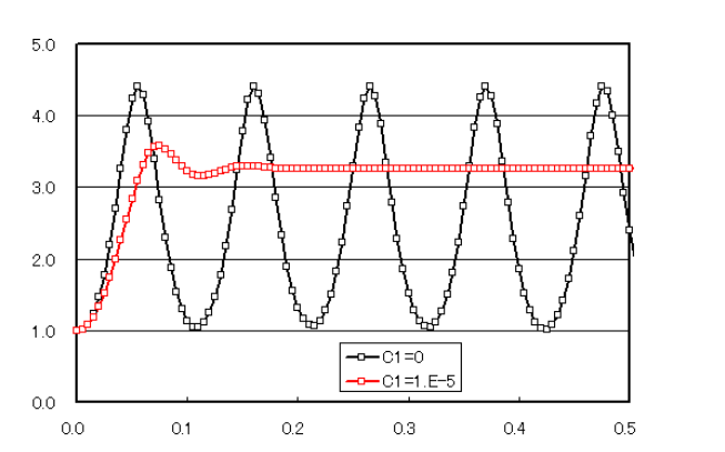
Fig.3 Rotor motion with no excitation
Next, the winding is excited with the rotor at the equilibrium stability point to simulate the starting process of the motor. The circuit system is the same as that used in " Analysis of DC brushless servo motors (using switch function)”. However, in "Analysis of DC brushless servo motors (using switch function)" the rotational speed is assumed to be constant, so the ON-OFF time of the switch is also input accordingly. However, in the initial stage of this analysis, the ON-OFF time cannot be given as an input because the speed changes from moment to moment. Therefore, a new function has been added to EMSolution to give the ON-OFF time of the switch with respect to the position, and this function is used.
In the analysis, the moment of inertia of the rotor is assumed to be 10-5 kg-m2 and a constant torque of 0.2 Nm is applied externally. The analysis starts from a stationary state with an initial position of 3.27 degrees. The position, velocity, and electromagnetic torque obtained from the analysis are shown in Figs. 4, 5, and 6, and reach a steady state in about $10 ms$, yielding a rotational speed of about $3800 deg/s (630 rpm)$. This result is consistent with the torque of about $0.2 Nm$ at $600 rpm$ analyzed in "Analysis of DC brushless servo motors (using switch function)". In addition, in the steady state, the speed fluctuation is about 10%.
As described above, by coupling the motions, various types of analysis, such as during motor startup, transient, or failure, can be performed. In addition to switches, the motion analysis can be performed by combining the circuit system elements of Network modules of various springs and dampers. Currently, only switches have position-dependent characteristics among the circuit system elements, but in principle, other elements can also have position- and velocity-dependent characteristics. If necessary, we would like to add such elements in the future, and we would be happy to receive your requests.
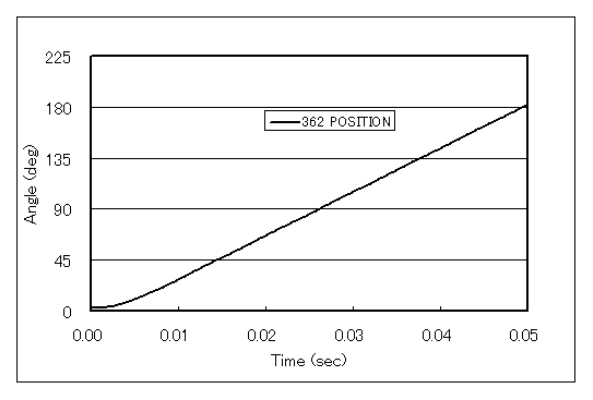
Fig.4 Rotor angle change at startup
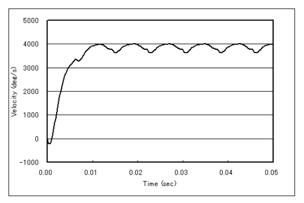
Fig.5 Rotor speed change at startup
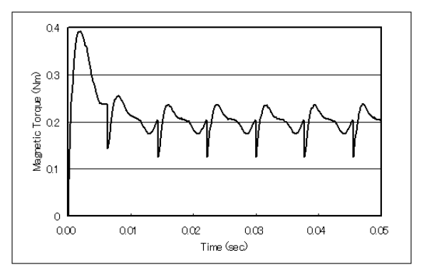
Fig.6 Electromagnetic force torque change of rotor at start up
How to use
The following illustrates how to input ON-OFF times for switch positions using an example of the switch data used in the startup analysis example above.
A new TIME_ID option has been added to the second column: TIME_ID=0 (no input allowed) represents ON-OFF with respect to time as before. If TIME_ID ≠ 0, then the time change data represented by TIME_ID is used as a parameter for ON-OFF. TIME_ID can be applied not only to equation-of-motion inputs but also to other time-varying data. For other inputs, the same as before, but with the exception of the ON-OFF time of the switch. However, the ON-OFF time of the switch is replaced with a position parameter. In this example, the switch is turned on between 15 and 75 degrees in a 180-degree cycle.
Next, set up the equation of motion input data for the above starting time analysis. Please refer to the Handbook "18.6 Equation of Motion Input" for details. The main input parameters are as follows
- INITIAL_POSITION = -3.26 degrees : Initial position
(position rotated 3.26 degrees clockwise from the position given in Fig. 1) - POSITION_ERROR =0.1 degree : Position calculation tolerance
- MASS =1.e-5$kgm^2$ : Moment of inertia
- CONSTANT_FORCE =0.2 $Nm$ : Constant torque from external source (counterclockwise)
- FORCE_TYPE =1: Use the electromagnetic torque of the rotor calculated by the sliding motion
- REGION_FACTOR =4: The electromagnetic force torque above is multiplied by REGION_FACTOR for analysis.
This must be entered because periodicity is not used for the analysis of motion.
Note : that when Dymanic analysis is performed, the position, velocity, and electromagnetic force for the computed time are output to motion file (Figs. 3, 4, and 5).
Download
Analysis Model
・ input_Cogging : For cogging (Fig.2) analysis
・ input_Equil : For analysis of motion to the equilibrium position (Fig. 3)
</br(when>(when C1=$1.0e-5$)
・ input_Static : For calculating initial values for startup analysis
To restart the startup calculation after the calculation is complete,
the solutions file name should be changed to old_solutions.
・ input_Start : For startup calculation
(Fig.4, 5, 6, input data example shown in "How to use")
・ pre_geom2D.neu : Stator mesh data
・ rotor_mesh2D.neu : Rotor mesh data
Analysis Examples by Functions
Analysis of permanent magnet motors
- Application of COIL to Motor Windings
- Impact Load Analysis of Brushless DC Servo Motor
- Dynamic Analysis of DC Brushless Servo Motor (ON-OFF function based on SWICH position)
- Analysis of DC brushless servo motors (using switch function)
- Three-Dimensional Cogging Torque Analysis for Permanent Magnet Motors
- Two-Dimensional Cogging Torque Analysis for Permanent Magnet Motors
©2020 Science Solutions International Laboratory, Inc.
All Rights reserved.