Electromagnetic field analysis software

Electromagnetic field analysis software
DC-field eddy current analysis method
- TOP >
- Analysis Examples by Functions (List) >
- DC-field eddy current analysis method
Summary
In this section, we discuss the equations in a conductor in constant motion.
Explanation
The equations for the other regions are exactly the same as in conventional static magnetic field analysis and are also handled in the same way. The $A$-$\phi$ method is used as in ordinary eddy current analysis. That is, the magnetic and electric fields are expressed by the magnetic vector potential $A$ and the electric scalar potential (time integral of $\phi$) $\Phi$ as follows
$$B = \nabla × A (1)$$
$$E = -\dot{A} – \nabla \dot{\Phi} (2)$$
The constitutive equation for a conductor in motion is expressed, as usual, by the following relationship where $\sigma$ is the electrical conductivity. Here we use a coordinate system fixed to the moving conductor, so the kinetic term in $\nu×B$ does not appear.
$$J = \sigma E (3) $$
Substituting equations (1), (2), and (3) into the following ampere law and current conservation equation,
$$\nabla \times H = J (4)$$
$$\nabla \cdot J = 0 (5)$$
then, the following governing equations to be solved are derived
$$\nabla \times \frac{1}{\mu} \nabla \times A + \sigma ( \dot{A} + \nabla \dot{\Phi} ) = 0 (6)$$
$$- \nabla \sigma ( \dot{A} + \nabla \dot{\Phi} ) = 0 (7)$$
In DC-filed eddy current analysis, the upwind difference is taken for the time derivative in equation (7). Suppose that the finite element mesh is equally divided in the direction of motion as shown in Fig. 1. In the case of rotational motion, equal angle division is assumed. The unknown variables for $A$ are assigned to the edges and the variables for $\Phi$ are assigned to the nodes. Denote the variable $A$ for edge $e$ by $A^e$ and the variable for node $n$ by $\Phi^n$. For edge $e$, denote the edge on the upwind side of the motion by one mesh by $\tilde{e}$ and for node $n$ by and $\tilde{n}$.
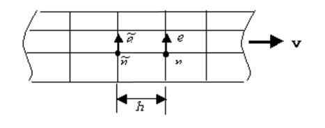
Fig.1 Element partitioning of a motion conductor
In this case, the upwind time difference is expressed as follows:
$$\dot{A^e} \approx \frac{1}{\delta t} ( A^e – A^{\tilde{e}} ) (8)$$
$$\dot{\Phi} \approx \frac{1}{\delta t} ( \Phi^n – \Phi^{\tilde{n}} ) (9)$$
where $\delta t$ is the time it takes for the conductor to move one mesh and is given by $h$/ν. Applying the Galerkin method to equation (6), equations (8) and (9) are used to solve the equation. The overall matrix is an asymmetric matrix, and the conventional ICCG method cannot be used; an asymmetric matrix solving method is required. In the formulation here, the $A$-$\phi$ method is used, but it can also be formulated using the $A$ method without $\phi$. In the above formulation, we only need to exclude $\Phi$. As in ordinary eddy current analysis, the $A$-$\phi$ method has more variables, but convergence is faster. In equation (2), we used the time integral of $\phi$, $\Phi$, to make the treatment of $A$ and $\phi$ the same as in the transient analysis in EMSolution, but we can also use $\phi$ directly. In this case, convergence seems to be the fastest. However, since the transient analysis handles equation (2), care must be taken when starting a transient analysis using the DC-field eddy current analysis results as the initial values. In other words, the following three types of handling can be selected in EMSolution.
(1)A法
$$E = – \dot{A} (10)$$
(2)A-Φ法
$$E = – \dot{A} – \nabla \dot{\Phi} (11)$$
(3)A-φ法
$$E = – \dot{A} – \nabla \phi (12)$$
The biconjugate gradient method with incomplete Cholesky decomposition (ILU Bi-CG method, ILU Bi-CGSTAB method, and ILU GPBi-CG method) is introduced as an asymmetric matrix solving method. Although the ILU GPBi-CG method seems to converge relatively well, the convergence is considerably less good than the conventional eddy current analysis using symmetric matrices. In particular, it may not converge when the elements are flattened.
Periodic boundary conditions are used in DC-field eddy current analysis. Periodic symmetry or periodic antisymmetry conditions can be used for linear or rotational motion. The mesh in the region where eddy currents are generated must be equally spaced in the direction of motion and equally angularly divided for rotational motion. The sliding method can also be used for this analysis. This allows transient analyses of linear and rotational motions to be performed using the results of the DC-field eddy current analysis as initial values. The method of execution is almost the same as the conventional method of using the static magnetic field analysis as the initial value. Nonlinear calculations can also be performed in the same way as in conventional static magnetic field analysis.
Analysis Examples by Functions
DC field current analysis
©2020 Science Solutions International Laboratory, Inc.
All Rights reserved.