Electromagnetic field analysis software

Electromagnetic field analysis software
Magnetic bearing model
- TOP >
- Analysis Examples by Functions (List) >
- Magnetic bearing model
Summary
Here is an example of analysis of the torque generated by a magnetic bearing during steady-state rotation.
Explanation
Assume that the magnetic bearing consists of axially stacked laminated iron and is anisotropically conductive with high electrical resistance to the axial direction. It rotates in the magnetic field generated by the coil and yoke as shown in Fig. 1. The model is vertically symmetric and periodically symmetric by 90 degrees. In this model, the axis radius is 120 mm and the gap between the axis and yoke is 0.4 mm.
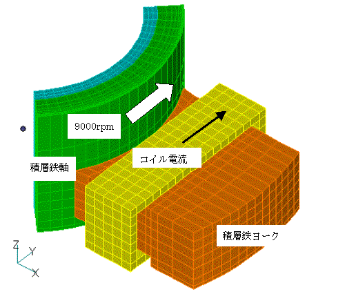
Fig.1 Magnetic bearing analysis model
The eddy current surface skin depth at 9000 rpm rotation is evaluated to be about 0.15 mm. Hence, the thickness of the surface layer division was set to 0.03 mm. When analyzing with such a thin element layer, the convergence of the asymmetric matrix solver is very slow. In this example, the ILUBi-CGSTAB method was used, and it took about 39,000 iterations, including nonlinear iterations, to achieve convergence to $10^{-8}$.
Figs. 2 and 3 show the magnetic field distribution on the rotating axis. The magnetic flux flows roughly from above to below the axis. The characteristic feature is that the magnetic field inside the axis is almost uniform in the direction of rotation, as can be seen in Fig. 3. Fluctuations in the magnetic field are limited to the surface. However, the fluctuations of the magnetic field penetrate more than the skin thickness. This is probably because the axial conductivity of the axis of rotation is assumed to be very small, so the magnetic field in the in-plane direction seeps into the interior. The variation of the axial magnetic field is limited to about the skin thickness. The magnetic field strength is high before and after the rotation direction of the poles, and the direction of the magnetic field is oriented in the direction of rotation (or vice versa).
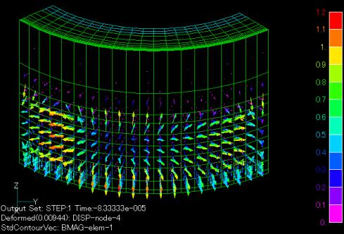
Fig.2 Magnetic flux density distribution in rotating shaft (unit T)
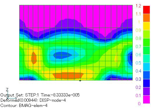
Fig.3 Magnetic flux density distribution on surface of rotating shaft (unit T)
Roughly speaking, the magnetic flux flows from above to below the axis. Characteristically, the magnetic field inside the axis is almost uniform in the direction of rotation, as can be seen in Figure 4. Fluctuations in the magnetic field are limited to the surface. However, the fluctuations of the magnetic field penetrate more than the skin thickness. This is probably because the axial conductivity of the axis of rotation is assumed to be very small, so the magnetic field in the in-plane direction seeps into the interior. The variation of the axial magnetic field is limited to about the skin thickness. The magnetic field strength is high before and after the rotation direction of the poles, and the direction of the magnetic field is oriented in the direction of rotation (or vice versa).
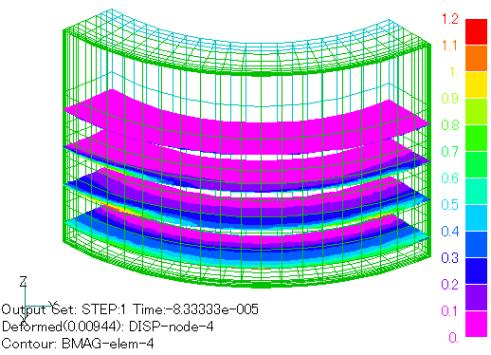
Fig.4 Magnetic flux density distribution of rotor cross section (unit T)
Figures 5 and 6 show the distribution of eddy currents. Eddy currents flow on the surface of the shaft. Due to the anisotropic nature of the conductivity, the current direction is mostly in the horizontal plane. Roughly, they flow in the direction that reduces the magnetic field fluctuation on the conductor surface.
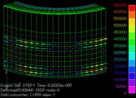
Fig.5 Current density distribution in rotating shaft (Unit: $A/m^2$ )
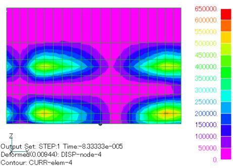
Fig.6 Current density distribution on surface of rotating shaft (Unit: $A/m^2$ )
IHI Corporation provided cooperation in the creation and analysis of this model.
Analysis Examples by Functions
DC field current analysis
©2020 Science Solutions International Laboratory, Inc.
All Rights reserved.