Electromagnetic field analysis software

Electromagnetic field analysis software
Rotating machine AC steady-state analysis in the presence of slippage
- TOP >
- Analysis Examples by Functions (List) >
- Rotating machine AC steady-state analysis in the presence of slippage
Summary
In "Analysis of Induction Motors", an AC steady-state analysis with slip as the initial value was used for the transient analysis. In this section, we would like to provide a supplemental explanation of this AC steady-state analysis.
Explanation
AC steady-state analysis with slip is calculated by fixing the rotor, which is actually rotating, and assuming that the frequency of the magnetic field received by the rotor from the stator side is s (slip coefficient) times the frequency of the stator side. The stator and rotor are generally not uniform in the direction of rotation, and the magnetic field contains harmonic components in the direction of rotation, but this is ignored and only the fundamental component is considered in the approximation. With this approximation, for example, if the rotor is synchronized with the stator magnetic field (s=0), the rotor appears to be in a static magnetic field. And if s=0.5, the rotor will feel a magnetic field with a frequency half the stator frequency. If we set the slip to s=2.0, which is greater than 1, the rotor will move in the opposite direction of the stator magnetic field and will feel twice the frequency (from r9.2, we can now enter a slip factor greater than 1). As mentioned above, this analysis method is only an approximate analysis. It is limited to linear analysis, of course, but it assumes uniformity of the structure in the direction of rotation and that the magnetic field produced by the stator is fundamental only. Therefore, when these assumptions do not hold, a transient analysis must be performed. Below we will look at the results of the AC steady-state analysis compared to the transient analysis, using the model presented in "Analysis of Induction Motors".
Fig. 1 shows the magnetic flux distribution at a current phase of 60 degrees in the stator winding with s=0.25. Fig. 2 shows the magnetic flux distribution at the same phase from a transient analysis including rotation. The zero-degree solution of the AC steady-state analysis is used as the initial value, and a linear analysis is performed. In this phase, the rotor is at $60 \times s = 15$ degrees. Comparing Figs. 1 and 2, there is a fairly good agreement, although the details are different. It can be seen that the AC steady-state analysis can also be used to evaluate the approximate magnetic field, etc. Fig.3 shows the variation of the magnetic field in a moving image. The magnetic field itself is rotating at the same speed as the stator field, but the stator is rotating at a speed of 1-s=3/4 compared to the magnetic field rotation. Similar analyses are shown in Figs. 4 and 5 for the case where the rotor is rotating in the opposite direction to the stator magnetic field at s=2.0. The relative velocities of the rotor and stator are large, and the induced currents in the rotor bars are large, resulting in a larger distortion of the magnetic field. The non-uniformity of the structure in the direction of motion due to the rotor bars and slots has a significant effect, and the difference between the AC steady-state analysis and the transient analysis is larger than in the previous analysis, but the agreement is still quite good.
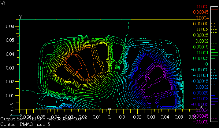
Fig.1 AC steady calculation
(s=0.25, Phase 60 deg)
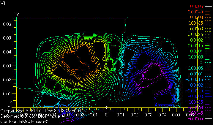
Fig.2 Transient calculation
(s=0.25, Phase 60 deg)

Fig.3 Time variation of magnetic flux by AC steady calculation(s=0.25)
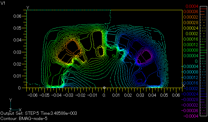
Fig.4 AC steady calculation
(s=2.0, Phase 62.7 deg)
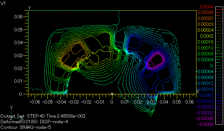
Fig.5 Transient calculation
(s=2.0, Phase 62.7 deg)
Analysis Examples by Functions
Sliding method
- Analysis with closed sliding surfaces
- Effect of Shape Data Accuracy on Sliding Method
- Use of external current magnetic field sources during slide motion analysis
- Analysis when the sliding surface includes the central axis of rotation
- Analysis using two sliding surfaces
- Rotating machine AC steady-state analysis in the presence of slippage
©2020 Science Solutions International Laboratory, Inc.
All Rights reserved.