Electromagnetic field analysis software

Electromagnetic field analysis software
Improvement of deformation motion function
- TOP >
- Analysis Examples by Functions (List) >
- Improvement of deformation motion function
Summary
Coupled analysis of EMSolution and motion that changes the distance between magnetic poles, such as the analysis of a plunger, is analyzed by deforming the elements in the surrounding air region. An example is shown in "Plunger Motion Analysis (Electromagnetic Field Analysis Coupling Motion and External Circuits)". In this case, two mesh data (pre_geom, deform_mesh) were needed to internalize the deformation location. The two meshes had to have different deformation locations, but the same element and nodal connections. Creating two such meshes was difficult, especially for 3D calculations. We are pleased to report that this improvement requires only one mesh, making it easier to use.
Explanation
In order to use this improved function, it is necessary to enclose the deformation area (light blue) with some elements (shown in red and called control elements) as shown in Figure 1. The nodes of the control elements must coincide with the nodes on the surfaces of the fixed and mobile parts. Also, the control element should not cross the original element.
Note that the control element must remain convex (the line connecting any two nodes must not extend outside the element) when the mobile part is moved. Figure 2 shows an example of element deformation during movement. The analysis results are the same as before. If the gap between the moving and fixed sections is very small, divide the gap and the deformed sections near the gap into as fine a mesh as possible. If the element is deformed too flatly, convergence will be very poor and the calculation may fail.
This method is also applicable to three-dimensional analysis. In this case, please prepare control elements of three-dimensional elements (primary hexahedron, tetrahedron, triangular prism). The original mesh may be a tetrahedron, and automatic mesh generation may be possible. However, each control element must contain elements inside and be connected at nodes on the surface. This functionality was released in EMSolution ver. 9.8.4.
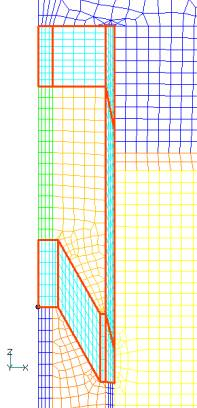
Fig.1 Control elements
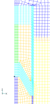
Fig.2 Deformation example
How to use
Prepare mesh data pre_geom.(2D). The mesh data contains control elements. As a change to the input file, enter the physical property number of the control element in CONTROL_ELM_MAT_ID. POSITION0 is the relative position of the pre_geom mesh as before. POSITION1 is the relative position of the nodal data to be created temporarily, not equal to POSITION0, but within the range of displacement. The calculation results are not dependent on POSITION1. Temporarily created nodal positions are output to deform_mesh (ATLAS format).
This data can also be executed from EMSI (conventional data can also be executed). If you wish to use deform_mesh as before, once PRE_PROCESSING is executed in EMSolution, deform_mesh(ATLAS) will be created. Then, using PRE_GEOM(ATLAS) with PRE_PROCESSING=0, CONTROL_ELM_MAT_ID=0, POST_DATA_FILE=2: ATLAS format, you can rerun the analysis using the conventional data format.
Download
Analysis Model
・ input : Input condition file
・ pre_geom2D.neu : Mesh file
Analysis Examples by Functions
Coupled equations of motion and external circuit systems
- Three-dimensional analysis of plunger-type electromagnets and hinged electromagnetic relays with deformation
- Reference position in mesh deformation motion analysis
- Improvement of deformation motion function
- Plunger motion analysis
- New functionality added to Dynamic module – Relative position dependence of mass and restart function –
©2020 Science Solutions International Laboratory, Inc.
All Rights reserved.