Electromagnetic field analysis software

Electromagnetic field analysis software
Nodal point output of Lorentz (J x B) forces
- TOP >
- Analysis Examples by Functions (List) >
- Nodal point output of Lorentz (J x B) forces
Summary
The force applied to a current flowing in a nonmagnetic conductor can be analyzed by the Lorentz (J x B) force. EMSolution has been able to output it in the past, but it could only output the force applied to the element or the average density of the force as an element quantity. On the other hand, in stress analysis, it is often the case that forces are applied as nodal forces. Therefore, it was necessary to convert them to nodal forces in order to use them in stress analysis. We are pleased to report that the Lorentz force can now be output at a nodal point.
Explanation
As a simple example, we calculate the electromagnetic force distribution when a current flows through a square cross section circular coil as shown in Fig. 1. The analysis is based on a 1/8 model using symmetry. A coil with a center radius of 1 m and a square cross section of 0.2 m $\times$ 0.2 m is assumed to carry a current of 2 MAT. The current distribution is given uniformly by the surface-defined current source (SDEFCOIL) and the distribution is shown in Fig. 1.
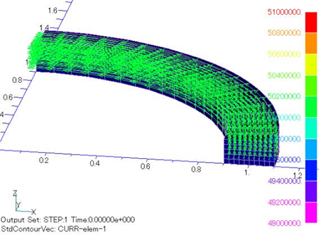
Fig.1 Analysis model and current density distribution in coil
Fig. 2 shows the calculated distribution of the electromagnetic force on the conductor surface, and Fig. 3 shows the vector diagram in the cross-section. In Fig. 2, you may notice that the force is not constant in the circumferential direction, even though the coil is axisymmetric. This is because the forces applied to the elements on the opposite sides of the plane of symmetry (in this case, the x=0, y=0, z=0 plane) are not added together. At the nodes on the plane of symmetry, the force is half. This would be the same input for the stress analysis, so the data can be used as input for the stress analysis.
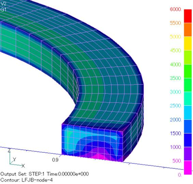
Fig.2 Absolute value distribution of force at conductor surface nodes due to Lorentz force
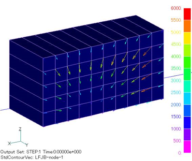
Fig.3 Distribution of forces on conductor cross section due to Lorentz force
Electromagnetic forces can also be analyzed by the nodal force method. Figs. 4 and 5 show the nodal forces obtained by the nodal force method, which are in good agreement with the corresponding Figs. 2 and 3. The nodal output from the nodal force method also uses the option of not adding symmetrically opposite forces together. This can be done by setting the output option parameter FORCE_NODAL to negative (-1 or -2) in the input file. If FORCE_NODAL is positive (1 or 2), the opposite symmetry is added and the distribution becomes axisymmetric, which looks natural.
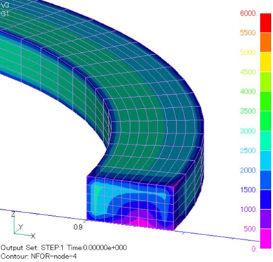
Fig.4 Absolute value distribution of forces at conductor surface nodes by nodal force method
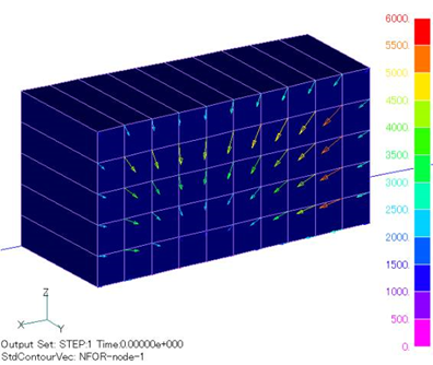
Fig.5 Distribution of forces on conductor cross section by nodal force method
As described above, for a nonmagnetic conductor, the Lorentz force and the force obtained by the nodal force method will be the same. If they differ, it is assumed that some error is involved. In the example above, the results are almost the same, but if the mesh is too coarse, the difference in forces will be larger. The air region around the conductor should also be reasonably well divided. In such cases, we recommend that you review the mesh.
If a strong magnetic field is externally applied to a conductor, the nodal force method may have a large force error because the accuracy of the force analysis is affected by the accuracy of the analysis of the strong magnetic field. In this case, large nodal forces appear even when there is no current flowing in the conductor. When obtaining the force by Lorentz force, the electromagnetic force is zero when no current is flowing, so the Lorentz force method is considered to be more accurate in such cases.
How to use
The output is obtained by setting NODE_OUT to 1 and FORCE_J_B to 1 or 2. The unit of electromagnetic force is N. As mentioned earlier, FORCE_NODAL must be set to -1 or -2 to obtain a nodal output using the nodal force method that is equivalent to the Lorentz force nodal output.
Download
Analysis Examples by Functions
Electromagnetic force
©2020 Science Solutions International Laboratory, Inc.
All Rights reserved.