Electromagnetic field analysis software

Electromagnetic field analysis software
A problem of in-plane nodal force of gap element
- TOP >
- Analysis Examples by Functions (List) >
- A problem of in-plane nodal force of gap element
Summary
In EMSolution, gap elements can approximate narrow gaps between magnetic materials. The use of gap elements avoids flat three-dimensional elements and reduces analysis time. In addition, by sandwiching a gap element of zero thickness, the attraction force between magnetic bodies when they are adsorbing (in contact) can be calculated. However, the electromagnetic force in the in-plane direction of the gap cannot be correctly obtained.
Explanation
Here we report on this issue through an example problem: Consider a two-dimensional analysis as shown in Fig. 1. Suppose that the two yokes, upper and lower, face each other as shown in the figure with a 1 mm air gap between them. When magnetic flux passes through the yokes due to coil current excitation, an attractive force acts between the yokes. It is also considered that the upper yoke is subjected to a force in the right direction and the lower yoke in the left direction. The analysis is performed with $H_t=0$ surface for the top and bottom as boundary conditions, and with antisymmetric periodic conditions for the left and right. Fig. 1 shows the analyzed magnetic flux density distribution superimposed.

Fig.1 Analysis model and magnetic flux density distribution
Fig. 2 shows the distribution of nodal forces when calculated without the gap element. As expected, the forces of attraction between the yokes and pulling the upper yoke to the right and the lower yoke to the left appear. The total force is 29.0 $N$ in the x-direction and -1413 $N$ in the y-direction (each per cm in thickness direction) for the upper yoke. The mesh looks rough, but when the mesh is made finer and checked, it has an accuracy of about 1%.
On the other hand, Fig. 3 shows the result when the gap element is used. The total is 10.1 $N$ in the x-direction and -1412 $N$ in the y-direction. The nodal forces in the y direction perpendicular to the gap element show very good agreement in distribution and total. However, the x-components in the in-plane direction do not match either the distribution or the total.
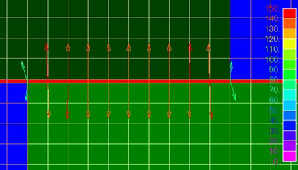
Fig.2 Nodal force distribution
(without gap element)
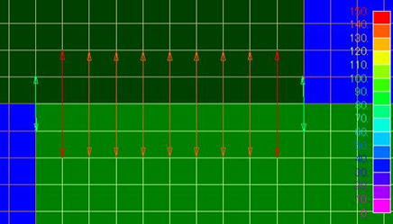
Fig.3 Nodal force distribution
(using gap element)
The reason for this result is that the gap element in EMSolution is treated as having only magnetic resistance, ignoring the thickness of the element. Basically, the magnetic field is assumed to be perpendicular to the element and the in-plane magnetic field is ignored. When determining the nodal force, the in-plane magnetic field is also included, assuming that the H of the in-plane magnetic field of the element in contact with both sides of the element is continuous, but this is not accurate.
To address this problem, we need to add a degree of freedom for the in-plane direction magnetic field. What is known as the foil element corresponds to this, and we hope to incorporate it into EMSolution in the future. Please be aware of this problem in the current situation and use the gap element. In other words, the electromagnetic force when using the gap element can be calculated with high accuracy for the attractive force between magnetic materials on both sides, but the in-plane directional electromagnetic force is far from accurate. For example, in the case of a motor torque calculation, if the gap element is placed in the stator and rotor to approximate the gap, the accuracy of the torque value is poor and the gap element cannot be used.
Download
Gap factor not used
・ input
・ pre_geom2D.neu : Mesh file
Gap Element Use
・ input
・ pre_geom2D.neu : Mesh file
Analysis Examples by Functions
Electromagnetic force
©2020 Science Solutions International Laboratory, Inc.
All Rights reserved.