Electromagnetic field analysis software

Electromagnetic field analysis software
Analysis by two-dimensional approximation
- TOP >
- Analysis Examples by Functions (List) >
- Analysis by two-dimensional approximation
Summary
The accuracy of the analysis and points to be considered in a two-dimensional analysis are explained using a sample model.
Explanation
In this section, we describe how to approximate the magnetic field analysis of a conductor that is long in one direction and subjected to a magnetic field orthogonal to it by a two-dimensional analysis. First, let us consider a three-dimensional analysis with a segmented model as shown in Fig. 1. The conductor has a cross section of 2cm × 2cm, a length of 20cm, and a magnetic field of 1T in the y direction is applied in alternating current. The conductor is copper with an electrical conductivity of $5.0 × 10^7 S/m$, and the applied magnetic field is assumed to vary at 50 Hz. The three-dimensional mesh is created by extending the two-dimensional mesh in the z-direction 2D_to_3D.
The 3D AC steady-state analysis of this problem yields the eddy current density distribution as shown in Fig. 2, and the current density distribution in the z-direction is shown in Figs. 3 and 4 as contours for phases 0 and -90 degrees. As can be seen from these figures, the current distribution is almost uniform in the z direction except at the edges of the conductor. This leads us to expect that a good approximation would be obtained with a two-dimensional calculation of the x-y cross section. In the three-dimensional analysis above, the number of elements reaches 12,000, and the convergence of the ICCG method is also quite poor due to the use of rather elongated elements. Considering the skin effect of conductors and conductors with more complicated cross-sectional geometries, the efficiency of the analysis would be greatly improved if the analysis could be done with two-dimensional calculations.
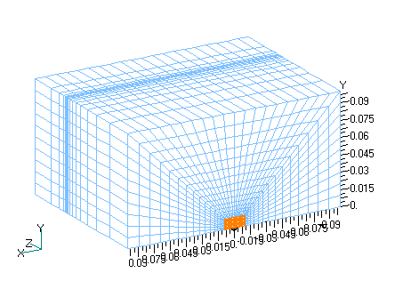
Fig. 1 Three-dimensional analysis mesh
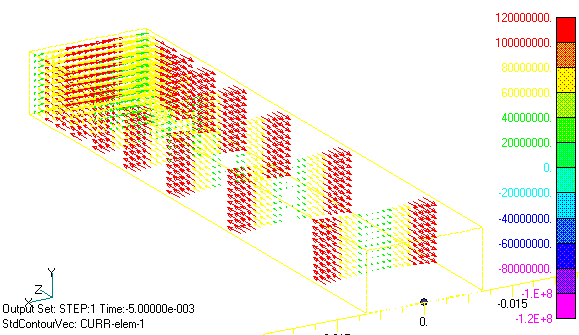
Fig.2 Eddy current density distribution
(phase-90 degrees)
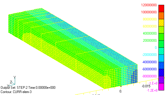
Fig.3 Current density distribution of eddy current in Z direction
(phase 0 degree)
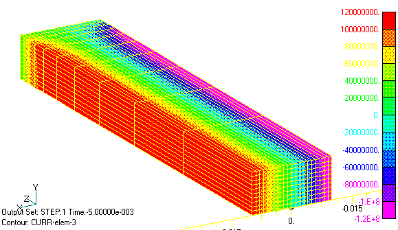
Fig.4 Current density distribution of eddy current in Z direction
(phase -90 degrees)
Now, we will perform an approximate analysis with two-dimensional calculations, but the important thing here is that the sum of the currents across the conductor cross section must be zero, and the bounding condition must be imposed. This condition can be imposed using EMSolution’s Surface Inflow Current Source (SUFCUR). This condition can be imposed by defining a SUFCUR on the conductor cross-section, connecting it to a constant current source, and setting its current to zero. If this condition is not imposed, the sum of the currents is generally not zero and depends on the applied magnetic field and boundary conditions. In the present analysis, the current is symmetric in the x=0 plane, so if we assume the Bn=0 boundary and analyze only the part where x is positive, the current will automatically be reversed in the opposite part, so the SUFCUR condition is not necessary. Figs. 5 and 6 show the two-dimensional eddy current density distribution in the z-direction. Figs. 5 and 6 correspond to Figs. 3 and 4 of the 3D analysis. It can be seen that the distributions in the cross section are in very good agreement. Figs. 7 and 8 show the magnetic flux density distribution. At phase 0°, the magnetic field is at its maximum and is distorted by eddy currents. The -90 degree is the point at which the applied magnetic field becomes zero, and the magnetic field that appears is due to eddy currents, which draw eddies.
The same analysis can be performed when many conductors are arranged in parallel. In this case, SUFCUR must be defined for each of the conductor cross-sections.
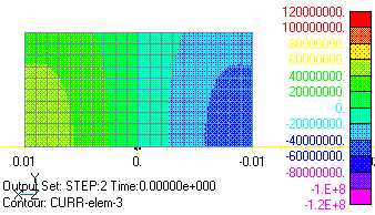
Fig.5 Two-dimensional analysis Current density distribution of eddy current in Z direction (phase 0 degrees), back side is in Z direction
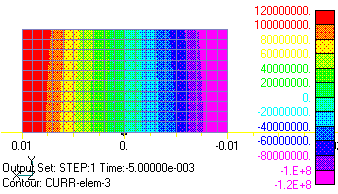
Fig.6 Two-dimensional analysis Eddy current current density distribution in Z direction (phase -90 degrees)
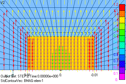
Fig.7 Magnetic flux density distribution (phase 0 degrees)
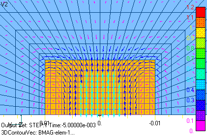
Fig.8 Magnetic flux density distribution (phase-90 degrees)
(Note) Here, a uniform magnetic field in the y direction is applied, but care must be taken with the input. Please see Q6 in the FAQ for more information on this. (The FAQ is available on the Users Only Wiki.)
Download
3D Analysis
・ input3D.ems
・ pre_geom2D.neu
・ 2D_to_3D
Two-dimensional analysis
・ input2D.ems
・ pre_geom2D.neu
Analysis Examples by Functions
Two dimensional analysis
- Analysis by two-dimensional approximation
- Computation of two-dimensional axisymmetric problems using pyramid (quadrilateral pyramid) elements
- Improvements to near-axis problems in axisymmetric calculations
- Division of a quadrangle element tangent to an axis at a single point into triangular elements
- Magnetic field analysis of solenoid coil
©2020 Science Solutions International Laboratory, Inc.
All Rights reserved.