Electromagnetic field analysis software

Electromagnetic field analysis software
Analysis of three-phase air transmission lines
- TOP >
- Analysis Examples by Functions (List) >
- Analysis of three-phase air transmission lines
Summary
Here the electrostatic field analysis function of EMSolution is introduced through a simple calculation example: Analysis of an air transmission line.
Explanation
A two-dimensional analysis of the cross section is performed with the overhead line as a straight line. Assume that the three-phase conductors (U, V, W) and the ground potential conductor (G) are arranged as shown in Fig. 1. The three-phase conductors are subjected to an effective AC voltage of 50 kV. y=0 is the ground surface and is assumed to have zero potential. The other outer boundaries are also assumed to have zero potential. The mesh around the conductor is as shown in Fig. 2. We define a surface element (or a line element in the two-dimensional case) for the conductor surface and give it a potential.
Fig. 3 and Fig. 4 show the distribution of the potential in air and the electric field strength at the ground surface. The ground surface is an iso-potential surface with zero potential, and the electric field is orthogonal to the ground surface.
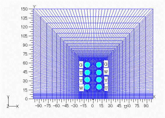
Fig.1 Mesh for air transmission line analysis

Fig.2 Mesh around conductor
Fig.3 Potential distribution
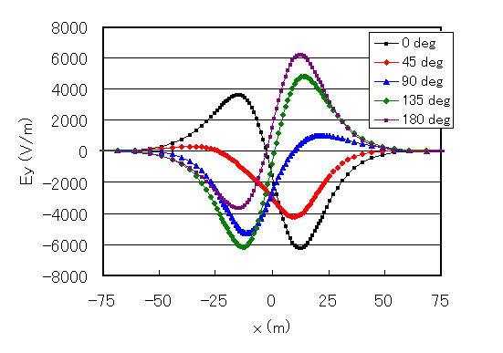
Fig.4 Electric field strength at ground surface
Download
Analysis Model
・ input
・ pre_geom2D.neu
Analysis Examples by Functions
Electrostatic field
©2020 Science Solutions International Laboratory, Inc.
All Rights reserved.